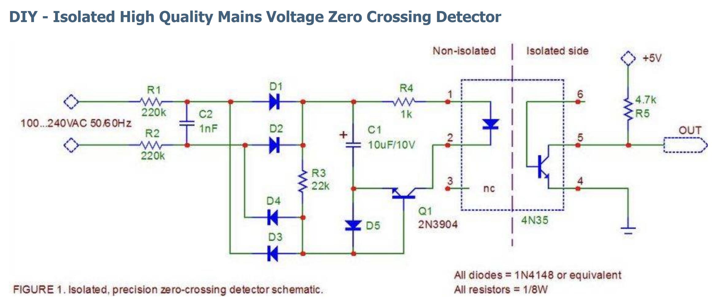
I'm considering using this zero-cross detector circuit in a design but I'm struggling to understand exactly how Q1 is activated. The description says "Q1 turns on and feeds current from C1 to the opto via R4, whenever the mains voltage (divided by (R1+R2)/R3) is lower than the voltage across C1." I understand this, but it doesn't explain how the base of Q1 is activated. In order for the optocoupler to indicate a zero crossing, the base must be activated only when a zero-crossing occurs, so its reasonable to assume that it has something to do with the capacitor discharging, but how it actually happens is still eluding me. Can anyone venture an answer?
Struggling to understand zero cross detecting circuit
Sean Dever
- 331
- 3
- 12

