I've been 2 days trying to design such amplifier with the help of a book of Boylestad (Electronic Devices and Circuit Theory), but the best I came with was an amplifier that amplifies what it's supposed to, but it's in cutoff, so I think it's not being well done (unless even being in cutoff, if it amplifies it's good enough? It's not, right?). The question is the following:
Project a tuned amplifier stage of intermeditate frequency using an adequate transistor with f0 = 455 kHz [f0 -> central frequency] and a bandwidth of 10.7 kHz. The amplifier must have a voltage gain of 34 dB to hold a load of 600 Ohm. Use a DC voltage source of 20 V.
I think the problem with what I'm doing might be the calculation of R_E and I_C. I'm very confused on how to calculate those 2. Though, as I've been trying for 2 days, I can't be sure the rest I did is correct or not (I also have already 4 versions of the things - and not more because I thought various on my head instead of writing not to take infinity resolving this). Could anyone point me in the right direction please? If any more information is needed just tell me and I'll try to provide it.
PS: I've tried to use the 2N2222 and the 2N3904, by the way. If a better one would be recommended, I'm all ears (or eyes, in this case haha).
Thanks in advance!
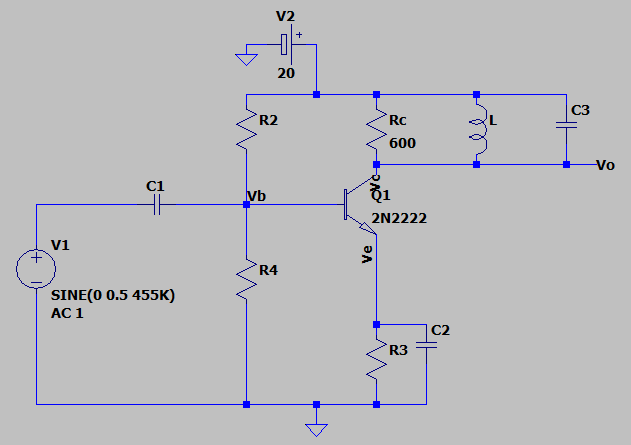
EDIT: I forgot to say, but it's a single tuned amplifier. In this case, it must have a resistor, a capacitor and a coil in the collector in paralell.
As per Andy aka request, this is schematic I've been using - though, any better alternatives on emitter or anywhere else are welcome:

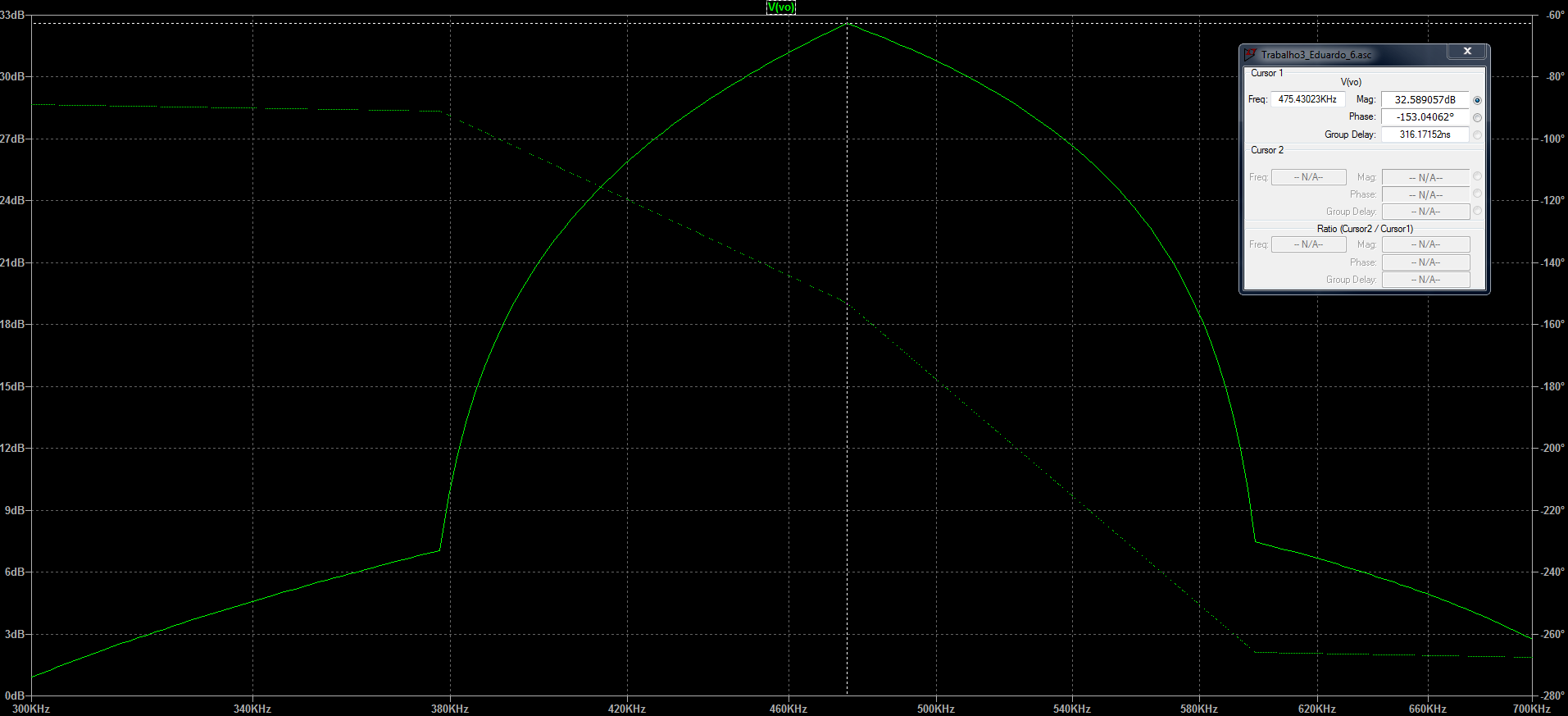
And the best I come up with is this (now correctly biased, but the bandwidth is still totally wrong):

After biasing this thing, I used 2 equations the professor talked about to find the capacitance of C3 and then to find the inductance of L:
\$BW = \frac{1}{{2\pi \times {R_C} \times C}} \Leftrightarrow 10700 = \frac{1}{{2\pi \times 600 \times C}} \Leftrightarrow C = 24.8{\rm{ }}nF\$
\${w_0} = 2\pi {f_0} = 2\pi \times 455 \times {10^3} = 2858.85 \times {10^3}{\rm{ }}{s^{ - 1}}\$
\${w_0} = \frac{1}{{\sqrt {LC} }} = 2858.85 \times {10^3} = \frac{1}{{\sqrt {L \times 28.8 \times {{10}^{ - 9}}} }} \Leftrightarrow L = 4.9 \times {10^{ - 9}} = 4.9{\rm{ }}\mu H\$
Though, I'm unsure about the \$2\pi\$ on the bandwidth formula. But I think it's without that, but with or without, it as a start, doesn't put the peek in 455 and then the final bandwidth is completely wrong. But I think it's without (any correction is welcomed). How can I put the transistor having the bandwidth I want? Was it not by putting the right values on the C1 and C3 capacitors with the \${f_{L/H}} = \frac{1}{{2\pi RC}}\$? If it's that, I've tried and I get nowhere...
