1
\$\begingroup\$

I've been 2 days trying to design such amplifier with the help of a book of Boylestad (Electronic Devices and Circuit Theory), but the best I came with was an amplifier that amplifies what it's supposed to, but it's in cutoff, so I think it's not being well done (unless even being in cutoff, if it amplifies it's good enough? It's not, right?). The question is the following:

Project a tuned amplifier stage of intermeditate frequency using an adequate transistor with f0 = 455 kHz [f0 -> central frequency] and a bandwidth of 10.7 kHz. The amplifier must have a voltage gain of 34 dB to hold a load of 600 Ohm. Use a DC voltage source of 20 V.

I think the problem with what I'm doing might be the calculation of R_E and I_C. I'm very confused on how to calculate those 2. Though, as I've been trying for 2 days, I can't be sure the rest I did is correct or not (I also have already 4 versions of the things - and not more because I thought various on my head instead of writing not to take infinity resolving this). Could anyone point me in the right direction please? If any more information is needed just tell me and I'll try to provide it.

PS: I've tried to use the 2N2222 and the 2N3904, by the way. If a better one would be recommended, I'm all ears (or eyes, in this case haha).

Thanks in advance!

EDIT: I forgot to say, but it's a single tuned amplifier. In this case, it must have a resistor, a capacitor and a coil in the collector in paralell.

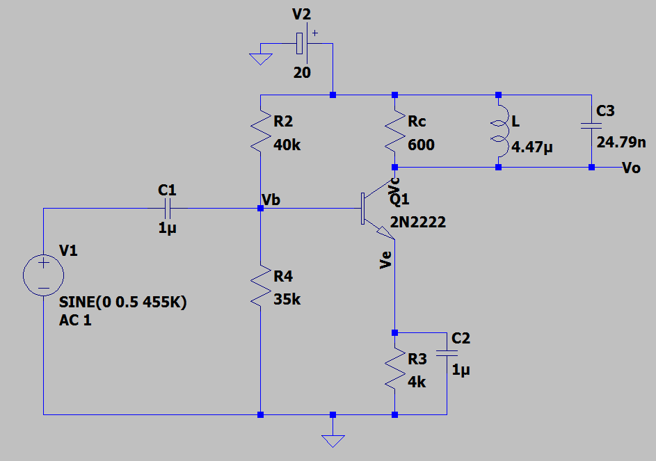
As per Andy aka request, this is schematic I've been using - though, any better alternatives on emitter or anywhere else are welcome. This is one of the versions that bias it correctly (one of the problems before was when I connected C3 and L, it would go on cutoff, but no more): The schematic I've been using
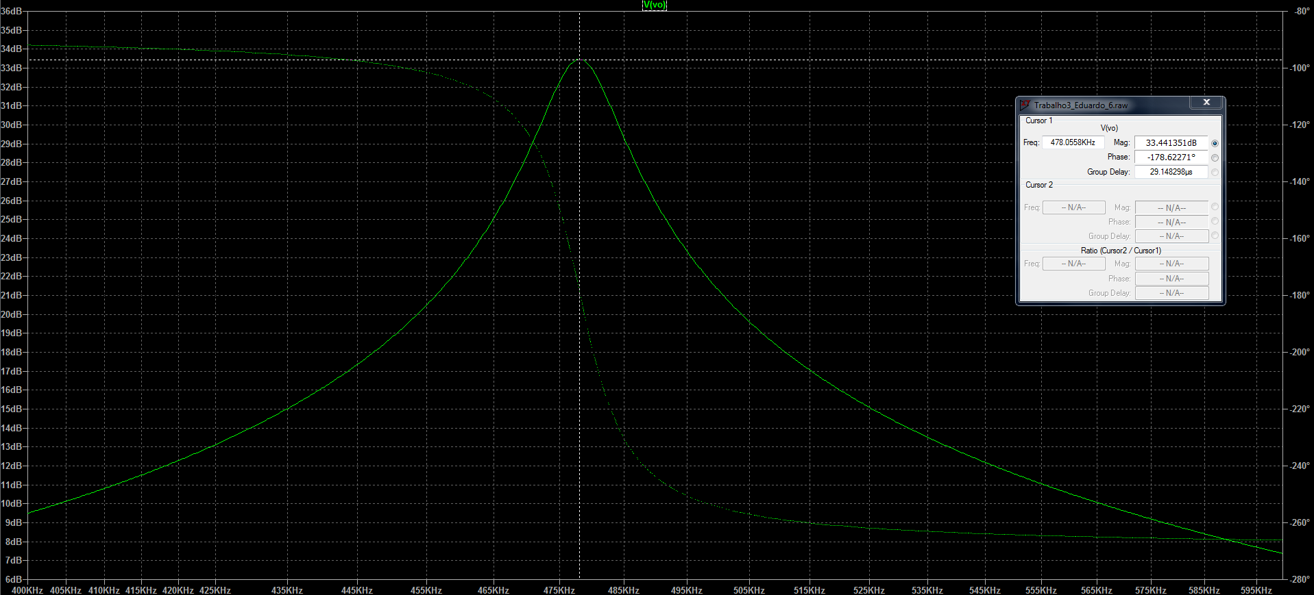
And the best I come up with is this (now correctly biased, but the bandwidth is still totally wrong): Graph
After biasing this thing, I used 2 equations the professor talked about to find the capacitance of C3 and then to find the inductance of L:

\$BW = \frac{1}{{2\pi \times {R_C} \times C}} \Leftrightarrow 10700 = \frac{1}{{2\pi \times 600 \times C}} \Leftrightarrow C = 24.8{\rm{ }}nF\$

\${w_0} = 2\pi {f_0} = 2\pi \times 455 \times {10^3} = 2858.85 \times {10^3}{\rm{ }}{s^{ - 1}}\$

\${w_0} = \frac{1}{{\sqrt {LC} }} = 2858.85 \times {10^3} = \frac{1}{{\sqrt {L \times 28.8 \times {{10}^{ - 9}}} }} \Leftrightarrow L = 4.9 \times {10^{ - 9}} = 4.9{\rm{ }}\mu H\$

Though, I'm unsure about the \$2\pi\$ on the bandwidth formula. But I think it's without that, but with or without, it as a start, doesn't put the peek in 455 and then the final bandwidth is completely wrong. But I think it's without (any correction is welcomed). How can I put the transistor having the bandwidth I want? Was it not by putting the right values on the C1 and C3 capacitors with the \${f_{L/H}} = \frac{1}{{2\pi RC}}\$? If it's that, I've tried and I get nowhere...

\$\endgroup\$
8
  • \$\begingroup\$ The first thing that crossed my mind is to use an RF BJT like the 2N5770. But its VCEO is 15V; not so good. The next thing is the 2SC4215 -- available and fairly cheap and VCEO of 30V. The main reason is the capacitance, at the frequency you are discussing, presents perhaps 10k or so with the 2N2222 and I'd be worried about incorporating it into the design. Since you appear to be allowed to select something with 20-30 times lower capacitance to it, why not? \$\endgroup\$
    – jonk
    Commented May 31, 2020 at 4:55
  • \$\begingroup\$ @jonk Sorry, I didn't get the part of the capacitance. Which capacitance are you talking about? If it's from the transistor itself, where did you see that on the datasheet? \$\endgroup\$
    – Edw590
    Commented May 31, 2020 at 14:45
  • \$\begingroup\$ @Andyaka I have posted the schematic I've been using. Though, better alternatives are welcomed. \$\endgroup\$
    – Edw590
    Commented May 31, 2020 at 14:46
  • \$\begingroup\$ Hmm yep, that's not that right. That's the load resistance. I called it Rc wrongly, my bad. Should be RL. It's the one asked to be 600, I guess? Or the 600 is the total from the entire paralell? (that might be one of the problems? Because the professor told us to design one, but we never actually made one having in consideration the coil and the capacitors value to have a specific bandwidth, this is the first one) \$\endgroup\$
    – Edw590
    Commented May 31, 2020 at 14:50
  • \$\begingroup\$ It's done. Sorry, I don't really know why I didn't put them there. Also, this is saying to avoid extended discussions in comments. Should I move this to a chat? \$\endgroup\$
    – Edw590
    Commented May 31, 2020 at 14:58

3 Answers 3

3
\$\begingroup\$

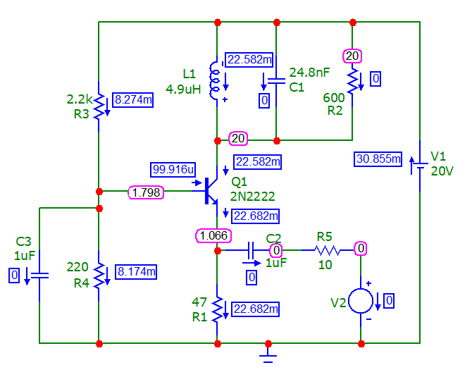
I don't think you'll get 34 dB gain with a common emitter amplifier and a load of 600 ohms. I'm not going to go through that process but I will show you what I did regards a common base amplifier because I think that might be your only option: -

enter image description here

The above simulation uses micro-cap 12 and the blue boxes show the DC operating currents and the magenta boxes show the various node voltages. I've used the 2N2222 BJT and the same values for L and C as the question calculated. The input is sourced at V2 and V1 in the spectrum below is the collector.

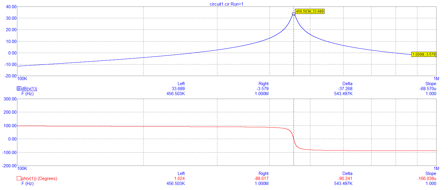
Here is the spectrum: -

enter image description here

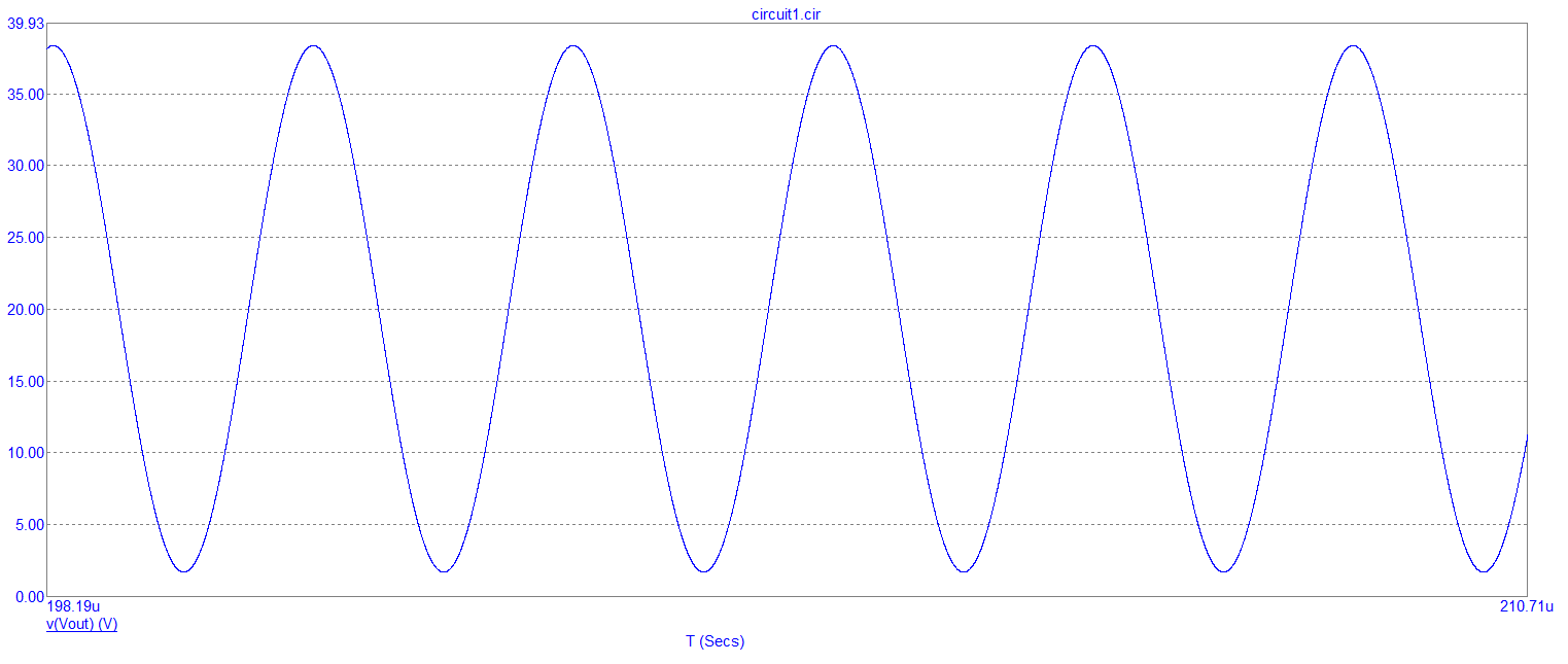
Gain is 33.7 dB at 456 kHz. Gain can be increased to 34 dB by lowering R5 a tad. Transient response looks good: -

enter image description here

The input peak level is 500 mV so it is being over-driven but the tuned circuit does a good job of restoring the sinewave shape.

I don't think you can "adequately" achieve your aims in common emitter but I'm prepared to eat my words and my shirt and hat.

There will be small-print associated with me eating my "stuff" but I'll hold onto that just in case someone tries to enforce it.

Where the basic problem lies

The big deal is a thing called \$r_E\$ - this resides inside the emitter of the BJT and it limits just how much gain can be achieved in CE or CB. If \$r_E\$ is 26 ohms (for example) then the maximum gain of the circuit is 600 ohm / 26 ohm = 27.3 dB (23.1) and well short of the 34 dB (50) required. So you have to make \$r_E\$ smaller.

To lower \$r_E\$ you need more collector current because: -

$$r_E = \text{26 mV}/ I_C $$

So, with Ic = 10 mA, \$r_E\$ is 2.6 ohms. With Ic at 1 mA, \$r_E\$ is 26 ohms and that can never give you a gain of 34 dB (given that the load is 600 ohms).

With your Re (R3) of 4000, you are miles away from getting a quiescent current of circa 10 mA or above. I estimate that you get a quiescent current of 2.16 mA and this make \$r_E\$ = 12 ohm and right at the limit. You need to get heavier handed with the quiescent current or use two transistors.

Good luck and I hope the bias points help.

\$\endgroup\$
1
  • 2
    \$\begingroup\$ Love the addition! \$\endgroup\$
    – jonk
    Commented May 31, 2020 at 18:17
1
\$\begingroup\$

So this needs an Rload of 600 ohms, plus another Rdamped in that 3-piece collector network. Assume the total R is 300 ohm, and you want gain of 50X,

That means the bipolar device transconductance is 1 / (300 ohms / Av = 50)) == 1/6 ohms.

Divide 0.026 volts by 6, and we learn the transistor should operate at 4.33 milliAmps. ROUND UP TO 5 MILLIAMPS.

Given the huge headroom ( 20 volts), I'd waste 5 volts across a emitter resistor, which you must bypass to << 4 ohms at the IF frequency.

\$\endgroup\$
1
  • \$\begingroup\$ Thank you. So I was able to bias it decently, finally. But, why do you say to assume 300 Ohm? What will happen that made you assume 300 and not the 600, for example? \$\endgroup\$
    – Edw590
    Commented May 31, 2020 at 14:20
0
\$\begingroup\$

So after infinity, me and a colleague came up with the solution. And actually, the main problem was approximations hahaha. In case anyone would like to know how it was done, it's like this. Also, I didn't understand why we did various things, but I'll have to ask for a questions session with the professor (or if anyone could explain why we did them, in case anyone would know, would be cool to have 2 explanations). Anyways, here is the solution.

---Data:---

\$f_0=455 kHz\$

\$BW=10.7 kHz\$

\$A_v=34 dB\$

\$R_L=R_C=600 Ω\$

\$V_{CC}=20V\$

\$h_{FE}=200\$

\$f_T>250 MHz\$

\$C_c=C_μ=25 pF\$

\$C_e=C_π=8 pF\$

---Calculate RLC:---

\$BW=\frac{1}{2π×R_c×C}⇔10700=\frac{1}{2π×600×C}⇔C=24.790×10^{-9}F = 24.790nF\$

\$w_0=2πf_0=2π×455×10^3=2,858,849.315 rad.s^{-1}\$

\$w_0=\frac{1}{\sqrt{LC}}⇔2,858,849.315×10^3=\frac{1}{\sqrt{L×24.790×10^{-9}}}⇔L=4.9355×10^{-3}=4.9355μH\$

---Calculus:---

\$f_T=\frac{g_m}{2π(C_π+C_μ)}≥n×f_0⇔\frac{g_m}{2π×8×10^{-12}}≥250×10^6⇔g_m≥0.052 S\$

\$A_v [dB]=34 dB\$

\$A_v [dB]=20×log⁡|A_v|⇔34=20×log⁡|A_v |⇔1.7=log⁡|A_v |⇔|A_v|=50,11⇔A_v=-50,11\$ (common emitter)

\$A_v=-g_m×R_C⇔-50.11=-g_m×600⇔g_m=0.0835 S\$

\$g_m=\frac{I_C}{V_T}⇔I_C=g_m×V_T=0.0835*25×10^{-3} = 2.09mA\$

\$I_C = I_E=2.09×10^{-3}A = 2.09 mA\$

\$I_C ≈ I_E = 2.09mA\$

For the transistor to be directly biased, \$V_{CE}≈10V\$

\$V_{CE}=V_{CC}-I_C×(R_C+R_E)⇔10=20-2.09×10^{-3}×(600+R_E)⇔R_E≅4.2kΩ\$

\$V_E=R_E×I_E≅4.2k×2.09m=8.8V\$

\$V_B=V_E+V_BE=8.8+0.7=9.5V\$

\$I_B=\frac{I_C}{h_{FE}}=\frac{2.09×10^{-3}}{200}()=10.4μA\$

\$R_2≤\frac{V_B}{10*I_B}=\frac{9.5}{10*1.04×10^{-5}}=91.35kΩ\$

We chose \$R_2=40.2kΩ\$ (market value)

\$V_B=\frac{R_2}{R_2+R_1}×V_{CC}⇔9.5=\frac{40.2k}{40.2k+R_1}×20⇔R_1=44,4kΩ\$

We chose \$R_1=44,2kΩ\$ (market value)

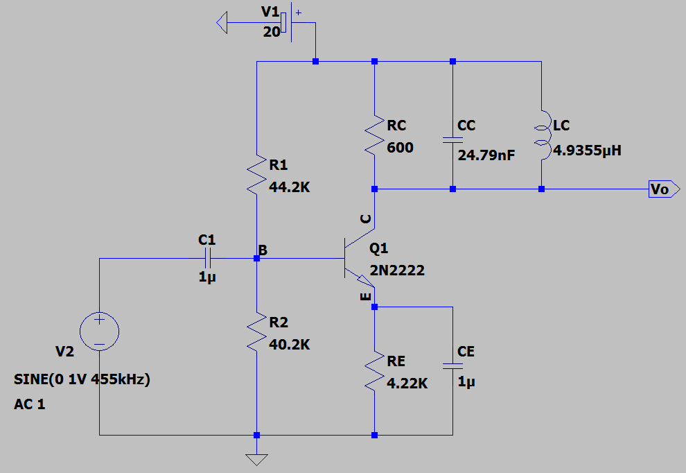
And this gives the following circuit:

enter image description here

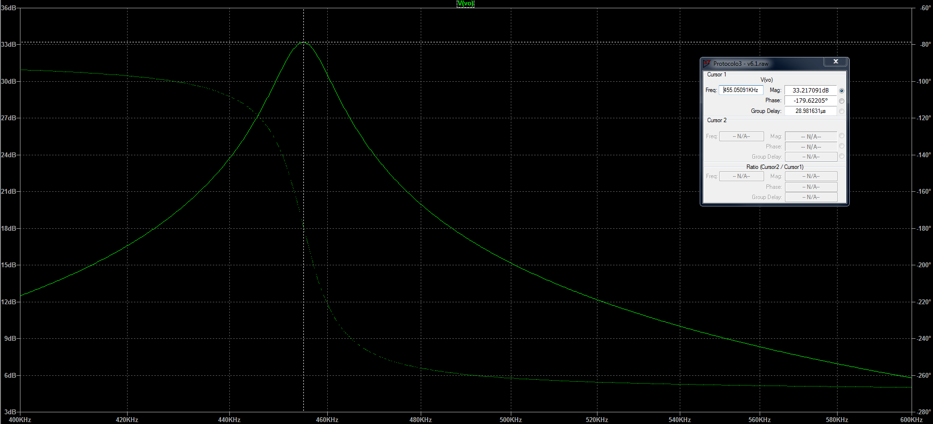
With the following gain graph:

enter image description here

And everything is perfect (except the gain is 33.2 dB and not 34 dB, but that's good enough).

Though, I still don't understand how the resistance \$R_L\$ for the formulas was calculated, why we used \$f_T\$ on this (actually, I don't know why that works), or I know why the BW formula works, since I think it's from \$BW = f_H - f_L == f_H\$, for \$f_L\$ being very small in comparision with \$f_H\$. But \$f_0=455 kHz\$ and \$BW=10.7 kHz\$, so \$f_L\$ and \$f_H\$ should be really close! Unless I don't get any of this even after having read the entire chapter of Boylestad's book (chapter 9) hahaha. I'll need to study this thing more somehow. But I just wanted to publish here the answer. Sorry for the big answer and possible mess... This was a work to do until yesterday, and for a week (not 3 days, that was the last time I restarted) I tried to make it and understand it. In the end I just made it to deliver it even if I didn't get what I was doing... So it stayed like that.

PS: I reviewed the recorded class and the professor actually told us to make it common emitter. I wasn't completely sure, but he said that. So it can't be Andy aka's answer. Though, thank you for having helped clearing some things in my mind (even though I now have other questions haha). I also made a version with the 600 Ohm being in \$R_L\$, which is out of the amplifier circuit, and it worked too. Still doubts though. But at least it's working.

UPDATE: So to clear my doubts that maybe might help someone...

  • The \$BW\$ formula comes from other place, harder to get to it;
  • First we make an untuned amplifier with the final gain we want and for a \$BW\$ large enough so we can have the tuned amplifier on \$f_0\$ with a bandwidth of what we want (in this case, \$f0 = 455 kHz\$ and \$BW = 10.7 kHz\$), but inside the \$BW\$ already made for the untuned amplifier. That's just "cut" the original bandwidth to the one we want and at the same time, choose the central frequency on what that's centered. The final \$f_0\$ and \$BW\$ we want must be far from the beggining and the end of the original \$BW\$ of the amplifier, or that will be losses in the gain;
  • Choosing the new values is done from the \$LC\$ part. First we choose the new \$BW\$ we want and use the \$BW\$ formula, which is related to the circuit's time constants. From there, we'll know the \$C\$ value for the capacitor. Then it's just choose the L value from the resonance frequency (\$f_0\$) formula;
  • \$R_L\$ worked inside or outside the circuit because this is AC part, so it doesn't matter where it is. There must be a resistance on the collector though, or the biasing will go away - at least from how this is made.

I've been waiting to understand this and to explain it here before accepting my own answer (and I've been really busy, so only now I got the time to review this and finally accept it). Hope it helps someone. Thank you for all the ones that answered and commented though, as they cleared other questions I had. Cheers!

\$\endgroup\$

Your Answer

By clicking “Post Your Answer”, you agree to our terms of service and acknowledge you have read our privacy policy.

Not the answer you're looking for? Browse other questions tagged or ask your own question.