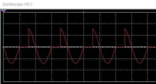
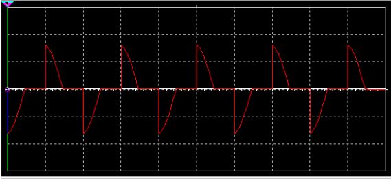
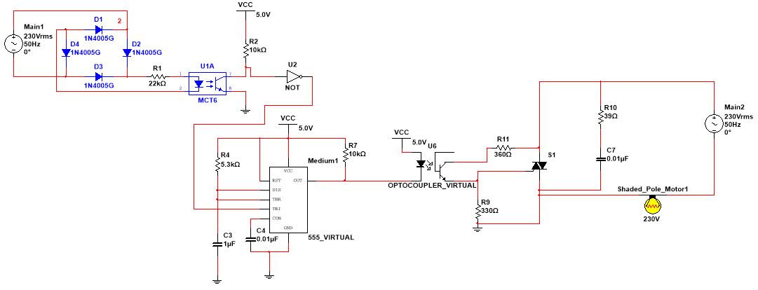
I have designed a speed control circuit for an induction motor. The circuit consists of a zero cross detector circuit whose output pulse is the input to a 555 timer. The 555 timer is used to generate a PWM wave that is then inputted into an optocoupler. The TRIAC control circuit then applies a chopped AC waveform to the induction motor. The 1st picture is the chopped waveform (incorrect) applied to the motor (used lamp in multisim as there is no motor), the 2nd picture is how the chopped waveform should look and the 3rd picture is the circuit diagram. I am having trouble (with the negative half cycle) with getting the waveform in the 1st picture to look like the correct waveform in the 2nd picture. Can you guys please help me fix the design?


How do I fix my induction motor speed control circuit?
Daelin Parmanand
- 3
- 2
