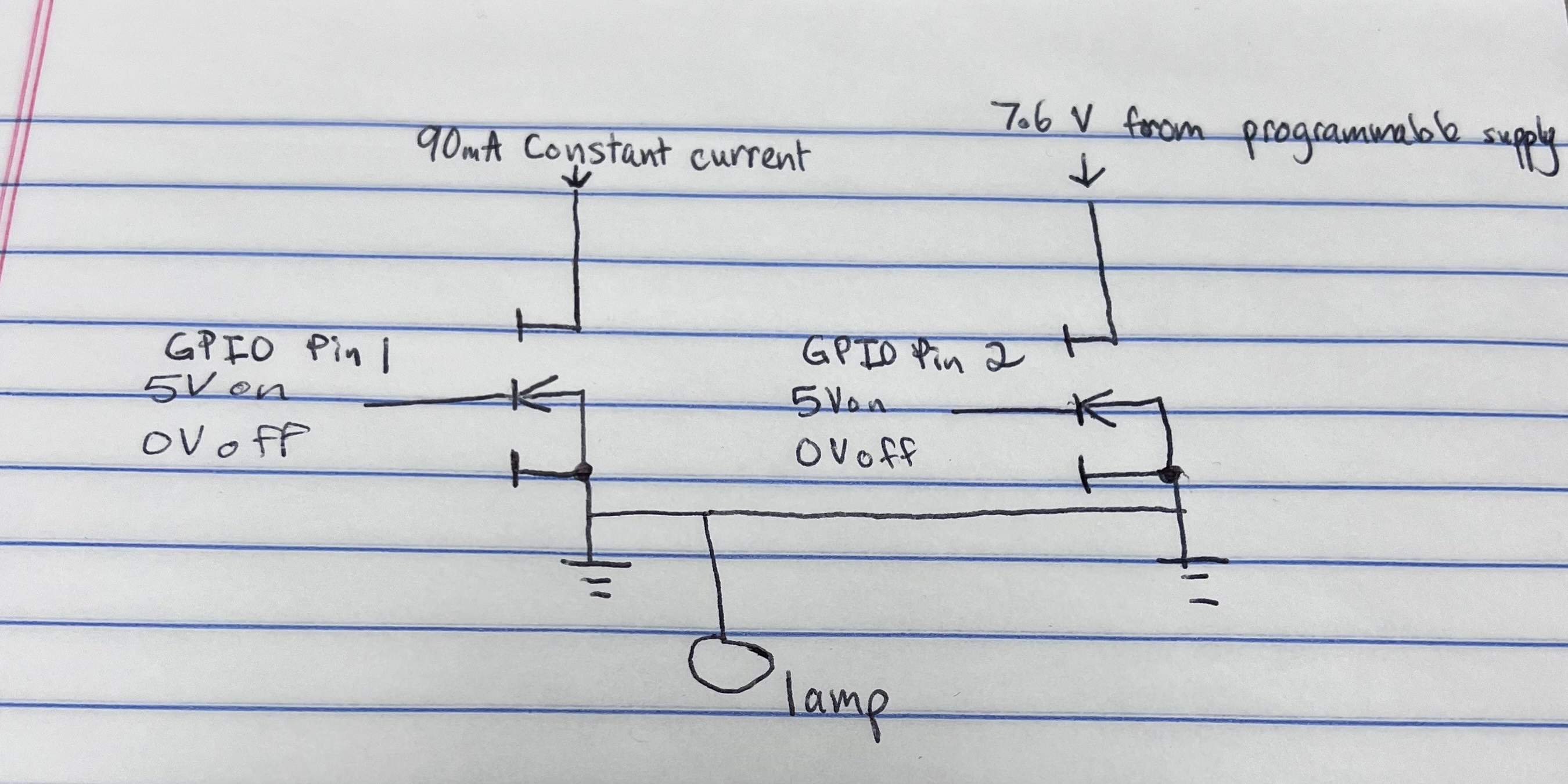
I need to switch between a constant current source and a programmable power supply to power a lamp.
For both sources, I need to apply 7.6 V to the drain and have the 7.6 V outputted to the lamp. The gates of the two MOSFETs will be controlled with two seperate GPIO pins. So when a logic HIGH level is applied to the gate of one MOSFET from the GPIO pin, the first source will be used and the other MOSFET would be off.
I have attached an image of the concept that I had in mind. I know the circuitry is incorrect but I was wondering if anyone knew the best way to do this.
Please note that I don't want to use relays.
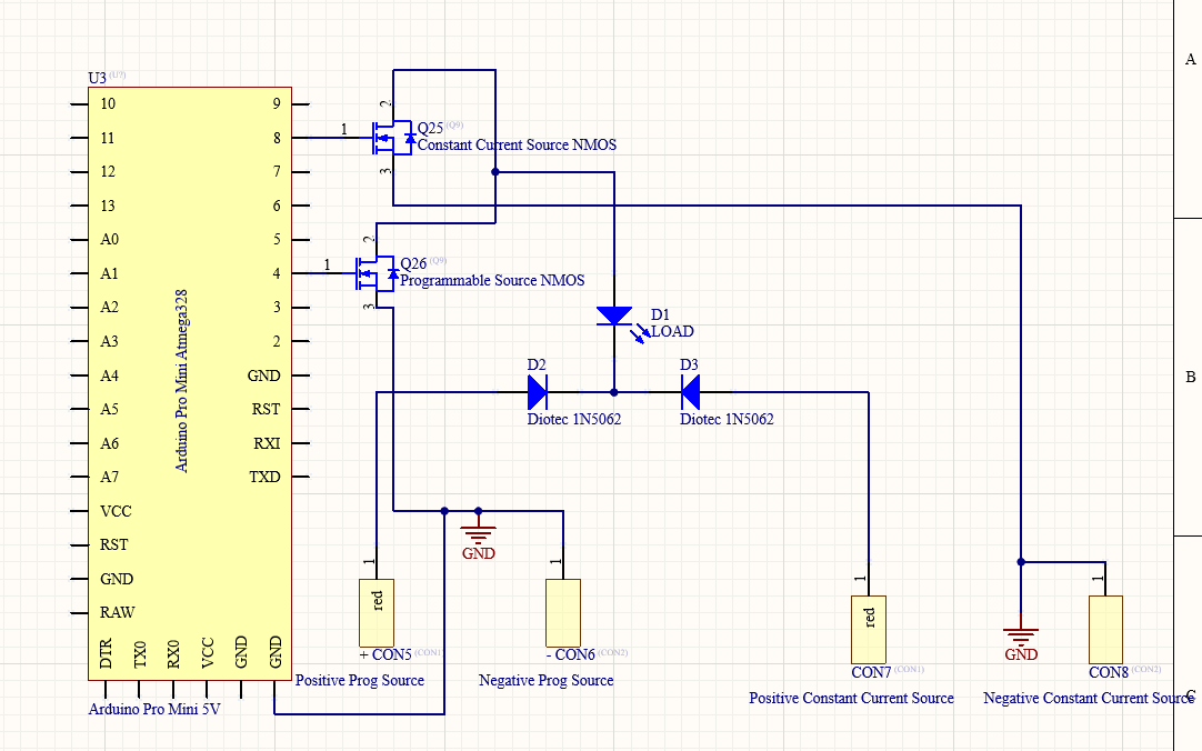
UPDATE: Before seeing the configuration that was commented on my post, I created a configuration of my own. The configuration is posted below. I replaced the load with a multimeter to make sure the correct values were being outputted to the load. When reading the voltage across the load everything seems to be switching correctly. However, when trying to read the current, my programmable source beeps every time a switch happens, and it seems as if current is being received from both supplies. I don't know what's causing this to happen and would greatly appreciate if someone could offer some advice.


