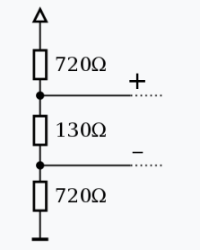
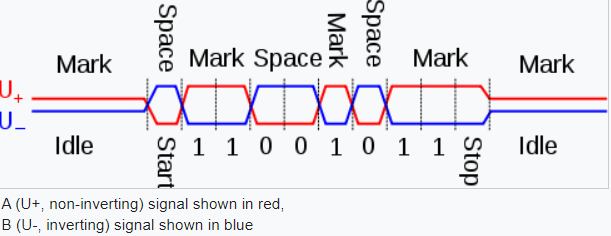
Figure 1. RS485 biasing network. Image by Stündle, Creative Commons. Note that both lines are biased positive and with the resistor values shown the + and - lines will be roughly 55% and 45% of supply voltage in the idle state.
From the same source:
Figure 2. Switching of the RS485 signal.
USB will be similar.
Or is it a case of the negative of the diff pair could be 0 - 2 V and the positive line 2 - 4 V (with respect to the actual USB ground)?
Generally not. The two inputs will be fed into a comparator and what you really want is polarity inversion at the inputs for clear logic levels. The signals are compared with each other rather than to an absolute reference.


