replaced http://electronics.stackexchange.com/ with https://electronics.stackexchange.com/
Source Link

Dear all StackExchange users,

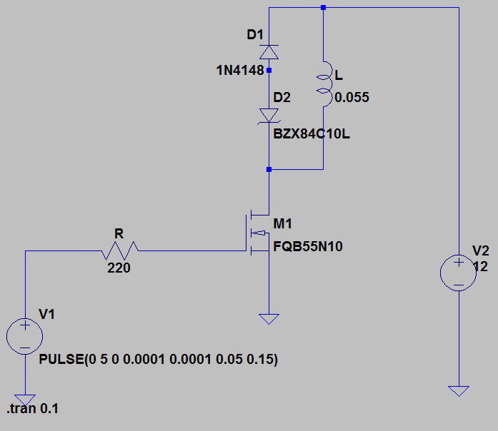
I want to make a circuit consisting of 8 valves. Each valve has 55mH and 33 ohm. I want to control them with an Arduino board and a proper MOSFET. Valves reaction time is 0.05ms and I want to drive them about 10 times per second, 5 times off and 5 times on. Valves are 12Vdc. The battery is also 12 Vdc.

I know that I have to add a sort of flyback diode to protect the MOSFET from high voltage while I switch each of the valves off. I know how a single flyback diode, flyback diode + resistor and a Zener & diode can protect it.

Also I know that Zener is much faster than a single diode.

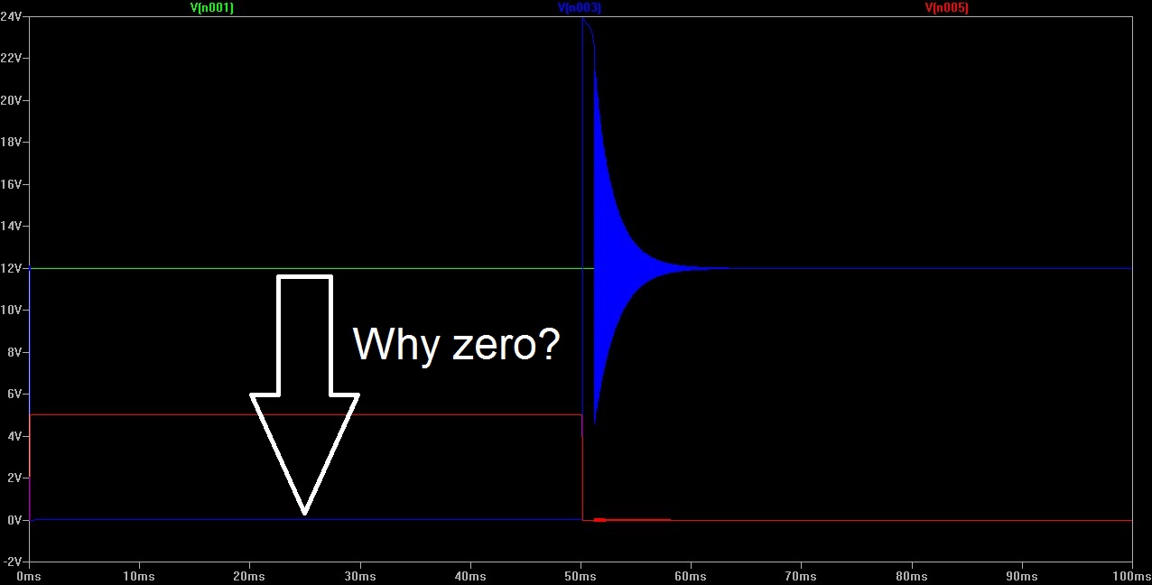
My main problem is that I don't know which part of I-t or V-t signal I should look to see the valve is turned off. I am using LTSpice. So I'd be thankful if you could guide me through this. In other words, When the valves are off after 5vdc is gone?!

Also in the simulation when I generate the 5vdc to MOSFET I see that the Voltage of the line that goes to ground is going from 12VDC to 0VDC. I really don't understand what's happening. Because when I connect the 12VDC directly to the coil and the coil to the ground, it remains 12VDC and doesn't go from 12VDC to zero!!

It is about 10 years since I passed electronics course in my bachelor years... so please forgive me if I am asking for the obvious.

Also I am coming from here "Can a Zener diode that protects a switch against inductance when the switch opens, affect turn on speed of the valve while you close it again?Can a Zener diode that protects a switch against inductance when the switch opens, affect turn on speed of the valve while you close it again?" Isn't the energy dissipation normal?
enter image description here

enter image description here

UPDATE: I checked the response time experimentally: 70v Zener = 8ms, with simple Diode 25ms.

Dear all StackExchange users,

I want to make a circuit consisting of 8 valves. Each valve has 55mH and 33 ohm. I want to control them with an Arduino board and a proper MOSFET. Valves reaction time is 0.05ms and I want to drive them about 10 times per second, 5 times off and 5 times on. Valves are 12Vdc. The battery is also 12 Vdc.

I know that I have to add a sort of flyback diode to protect the MOSFET from high voltage while I switch each of the valves off. I know how a single flyback diode, flyback diode + resistor and a Zener & diode can protect it.

Also I know that Zener is much faster than a single diode.

My main problem is that I don't know which part of I-t or V-t signal I should look to see the valve is turned off. I am using LTSpice. So I'd be thankful if you could guide me through this. In other words, When the valves are off after 5vdc is gone?!

Also in the simulation when I generate the 5vdc to MOSFET I see that the Voltage of the line that goes to ground is going from 12VDC to 0VDC. I really don't understand what's happening. Because when I connect the 12VDC directly to the coil and the coil to the ground, it remains 12VDC and doesn't go from 12VDC to zero!!

It is about 10 years since I passed electronics course in my bachelor years... so please forgive me if I am asking for the obvious.

Also I am coming from here "Can a Zener diode that protects a switch against inductance when the switch opens, affect turn on speed of the valve while you close it again?" Isn't the energy dissipation normal?

enter image description here

enter image description here

UPDATE: I checked the response time experimentally: 70v Zener = 8ms, with simple Diode 25ms.

added 101 characters in body
Source Link
arudino.tyro
  • 694
  • 2
  • 11
  • 22

Dear all StackExchange users,

I want to make a circuit consisting of 8 valves. Each valve has 55mH and 33 ohm. I want to control them with an Arduino board and a proper MOSFET. Valves reaction time is 0.05ms and I want to drive them about 10 times per second, 5 times off and 5 times on. Valves are 12Vdc. The battery is also 12 Vdc.

I know that I have to add a sort of flyback diode to protect the MOSFET from high voltage while I switch each of the valves off. I know how a single flyback diode, flyback diode + resistor and a Zener & diode can protect it.

Also I know that Zener is much faster than a single diode.

My main problem is that I don't know which part of I-t or V-t signal I should look to see the valve is turned off. I am using LTSpice. So I'd be thankful if you could guide me through this. In other words, When the valves are off after 5vdc is gone?!

Also in the simulation when I generate the 5vdc to MOSFET I see that the Voltage of the line that goes to ground is going from 12VDC to 0VDC. I really don't understand what's happening. Because when I connect the 12VDC directly to the coil and the coil to the ground, it remains 12VDC and doesn't go from 12VDC to zero!!

It is about 10 years since I passed electronics course in my bachelor years... so please forgive me if I am asking for the obvious.

Also I am coming from here "Can a Zener diode that protects a switch against inductance when the switch opens, affect turn on speed of the valve while you close it again?" Isn't the energy dissipation normal?

enter image description here

enter image description here

UPDATE: I checked the response time experimentally: 70v Zener = 8ms, with simple Diode 25ms.

Dear all StackExchange users,

I want to make a circuit consisting of 8 valves. Each valve has 55mH and 33 ohm. I want to control them with an Arduino board and a proper MOSFET. Valves reaction time is 0.05ms and I want to drive them about 10 times per second, 5 times off and 5 times on. Valves are 12Vdc. The battery is also 12 Vdc.

I know that I have to add a sort of flyback diode to protect the MOSFET from high voltage while I switch each of the valves off. I know how a single flyback diode, flyback diode + resistor and a Zener & diode can protect it.

Also I know that Zener is much faster than a single diode.

My main problem is that I don't know which part of I-t or V-t signal I should look to see the valve is turned off. I am using LTSpice. So I'd be thankful if you could guide me through this. In other words, When the valves are off after 5vdc is gone?!

Also in the simulation when I generate the 5vdc to MOSFET I see that the Voltage of the line that goes to ground is going from 12VDC to 0VDC. I really don't understand what's happening. Because when I connect the 12VDC directly to the coil and the coil to the ground, it remains 12VDC and doesn't go from 12VDC to zero!!

It is about 10 years since I passed electronics course in my bachelor years... so please forgive me if I am asking for the obvious.

Also I am coming from here "Can a Zener diode that protects a switch against inductance when the switch opens, affect turn on speed of the valve while you close it again?" Isn't the energy dissipation normal?

enter image description here

enter image description here

UPDATE: I checked the response time experimentally: 70v Zener = 8ms, with simple Diode 25ms.

Source Link
arudino.tyro
  • 694
  • 2
  • 11
  • 22

How does flyback diode decrease the response time of a solenoid valve

Dear all StackExchange users,

I want to make a circuit consisting of 8 valves. Each valve has 55mH and 33 ohm. I want to control them with an Arduino board and a proper MOSFET. Valves reaction time is 0.05ms and I want to drive them about 10 times per second, 5 times off and 5 times on. Valves are 12Vdc. The battery is also 12 Vdc.

I know that I have to add a sort of flyback diode to protect the MOSFET from high voltage while I switch each of the valves off. I know how a single flyback diode, flyback diode + resistor and a Zener & diode can protect it.

Also I know that Zener is much faster than a single diode.

My main problem is that I don't know which part of I-t or V-t signal I should look to see the valve is turned off. I am using LTSpice. So I'd be thankful if you could guide me through this. In other words, When the valves are off after 5vdc is gone?!

Also in the simulation when I generate the 5vdc to MOSFET I see that the Voltage of the line that goes to ground is going from 12VDC to 0VDC. I really don't understand what's happening. Because when I connect the 12VDC directly to the coil and the coil to the ground, it remains 12VDC and doesn't go from 12VDC to zero!!

It is about 10 years since I passed electronics course in my bachelor years... so please forgive me if I am asking for the obvious.

Also I am coming from here "Can a Zener diode that protects a switch against inductance when the switch opens, affect turn on speed of the valve while you close it again?" Isn't the energy dissipation normal?

enter image description here

enter image description here