after more research and experiments.
Source Link
Ivy Growing
  • 335
  • 4
  • 13

Please, help to figure out the pinout of microwave motion sensor FC1816.

The seller "doesn't understand" what it is required on queries to provide the pinout for the module. The module is the smallest microwave motion sensor I found, so it's very welcomed to run it.

I followed traces to find the function of 4 pins of 5. Please, help me to understand last pin. UPD: This question solved. Other question arose below...

FC1816 microwave motion detector

From left to right:

  • Pin 1: Out, connected to pin 2 of BISS0001.
  • Pin 2: Vcc, connected to pin 8 of BISS0001.
  • Pin 3: Enable, connected to pin 9 of BISS0001. Short it to GND should run the BISS.
  • Pin 4: Gnd, connected to pin 7 of BISS0001.
  • Pin 5: UPD: Vcc of microwave generator.

I have tried to connect both Vcc together to +5V, Enable to Vcc via 2k resistor (pullup), ground as regular. The out gives always logical 1.

What voltage should be supplied? BISS0001 supports up to 5V.

Please, help to figure out the pinout of microwave motion sensor FC1816.

The seller "doesn't understand" what it is required on queries to provide the pinout for the module. The module is the smallest microwave motion sensor I found, so it's very welcomed to run it.

I followed traces to find the function of 4 pins of 5. Please, help me to understand last pin.

FC1816 microwave motion detector

From left to right:

  • Pin 1: Out, connected to pin 2 of BISS0001.
  • Pin 2: Vcc, connected to pin 8 of BISS0001.
  • Pin 3: Enable, connected to pin 9 of BISS0001. Short it to GND should run the BISS.
  • Pin 4: Gnd, connected to pin 7 of BISS0001.
  • Pin 5: UPD: Vcc of microwave generator.

I have tried to connect both Vcc together to +5V, Enable to Vcc via 2k resistor (pullup), ground as regular. The out gives always logical 1.

What voltage should be supplied? BISS0001 supports up to 5V.
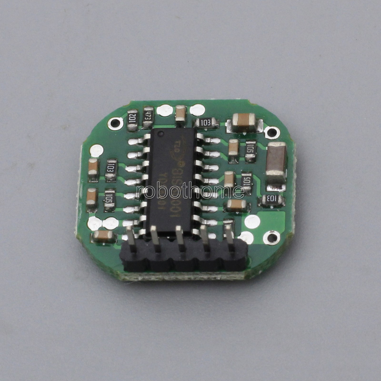
Please, help to figure out the pinout of microwave motion sensor FC1816.

The seller "doesn't understand" what it is required on queries to provide the pinout for the module. The module is the smallest microwave motion sensor I found, so it's very welcomed to run it.

I followed traces to find the function of 4 pins of 5. Please, help me to understand last pin. UPD: This question solved. Other question arose below...

FC1816 microwave motion detector

From left to right:

  • Pin 1: Out, connected to pin 2 of BISS0001.
  • Pin 2: Vcc, connected to pin 8 of BISS0001.
  • Pin 3: Enable, connected to pin 9 of BISS0001. Short it to GND should run the BISS.
  • Pin 4: Gnd, connected to pin 7 of BISS0001.
  • Pin 5: UPD: Vcc of microwave generator.

I have tried to connect both Vcc together to +5V, Enable to Vcc via 2k resistor (pullup), ground as regular. The out gives always logical 1.

What voltage should be supplied? BISS0001 supports up to 5V.

after more research and experiments.
Source Link
Ivy Growing
  • 335
  • 4
  • 13

Please, help to figure out the pinout of microwave motion sensor FC1816.

The seller "doesn't understand" what it is required on queries to provide the pinout for the module. The module is the smallest microwave motion sensor I found, so it's very welcomed to run it.

I followed traces to find the function of 4 pins of 5. Please, help me to understand last pin.

FC1816 microwave motion detector

From left to right:

  • Pin 1: Out, connected to pin 2 of BISS0001.
  • Pin 2: Vcc, connected to pin 8 of BISS0001.
  • Pin 3: Enable, connected to pin 9 of BISS0001. Short it to GND should run the BISS.
  • Pin 4: Gnd, connected to pin 7 of BISS0001.
  • Pin 5: ???, connected to analog circuitUPD: Vcc of microwave generator.

I have tried to connect both Vcc together to +5V, Enable to Vcc via 2k resistor (pullup), ground as regular. The out gives always logical 1.

What voltage should be supplied? BISS0001 supports up to 5V.

Please, help to figure out the pinout of microwave motion sensor FC1816.

The seller "doesn't understand" what it is required on queries to provide the pinout for the module. The module is the smallest microwave motion sensor I found, so it's very welcomed to run it.

I followed traces to find the function of 4 pins of 5. Please, help me to understand last pin.

FC1816 microwave motion detector

From left to right:

  • Pin 1: Out, connected to pin 2 of BISS0001.
  • Pin 2: Vcc, connected to pin 8 of BISS0001.
  • Pin 3: Enable, connected to pin 9 of BISS0001. Short it to GND should run the BISS.
  • Pin 4: Gnd, connected to pin 7 of BISS0001.
  • Pin 5: ???, connected to analog circuit.

Please, help to figure out the pinout of microwave motion sensor FC1816.

The seller "doesn't understand" what it is required on queries to provide the pinout for the module. The module is the smallest microwave motion sensor I found, so it's very welcomed to run it.

I followed traces to find the function of 4 pins of 5. Please, help me to understand last pin.

FC1816 microwave motion detector

From left to right:

  • Pin 1: Out, connected to pin 2 of BISS0001.
  • Pin 2: Vcc, connected to pin 8 of BISS0001.
  • Pin 3: Enable, connected to pin 9 of BISS0001. Short it to GND should run the BISS.
  • Pin 4: Gnd, connected to pin 7 of BISS0001.
  • Pin 5: UPD: Vcc of microwave generator.

I have tried to connect both Vcc together to +5V, Enable to Vcc via 2k resistor (pullup), ground as regular. The out gives always logical 1.

What voltage should be supplied? BISS0001 supports up to 5V.

Source Link
Ivy Growing
  • 335
  • 4
  • 13

Pinout of microwave motion sensor FC1816

Please, help to figure out the pinout of microwave motion sensor FC1816.

The seller "doesn't understand" what it is required on queries to provide the pinout for the module. The module is the smallest microwave motion sensor I found, so it's very welcomed to run it.

I followed traces to find the function of 4 pins of 5. Please, help me to understand last pin.

FC1816 microwave motion detector

From left to right:

  • Pin 1: Out, connected to pin 2 of BISS0001.
  • Pin 2: Vcc, connected to pin 8 of BISS0001.
  • Pin 3: Enable, connected to pin 9 of BISS0001. Short it to GND should run the BISS.
  • Pin 4: Gnd, connected to pin 7 of BISS0001.
  • Pin 5: ???, connected to analog circuit.