First things first. Grab yourself a copy of the BISS0001 datasheet.
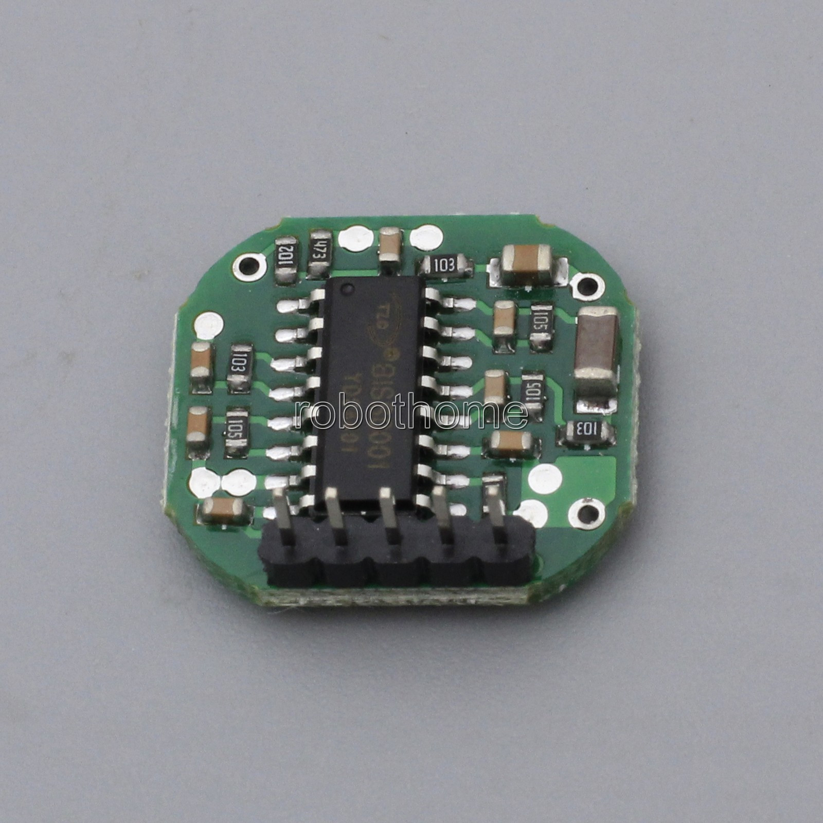
To understand what was going on I traced the signal line from the microwave IC to the BISS
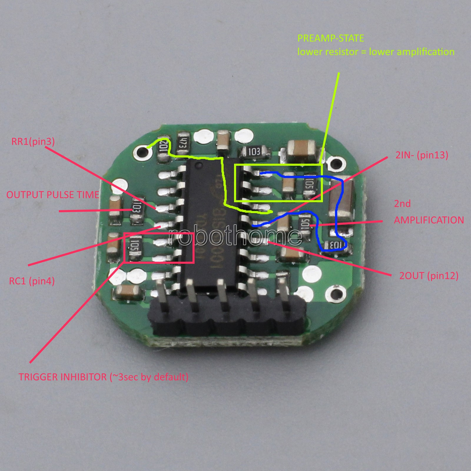
- signal comes from top left corner (green)
- then enters preamp stage on pin14 (green)
- goes from pin 16 to pin 13 .. 2nd amplification stage (blue)
- goes from 2OUT to internal comparator
The comparator does following ..
- signal should be around V2 ~ (1/2 VCC)
- if the signal goes above VH or VL (i guess 0.3*VCC and 0.7*VCC) the output is triggert

But .. what the hell is wrong? Why does the output stay always high? The problem (in my oppinion is the output amplitude of the 2nd amplification stage which higher then expected, maybe due to some noice or whatever).
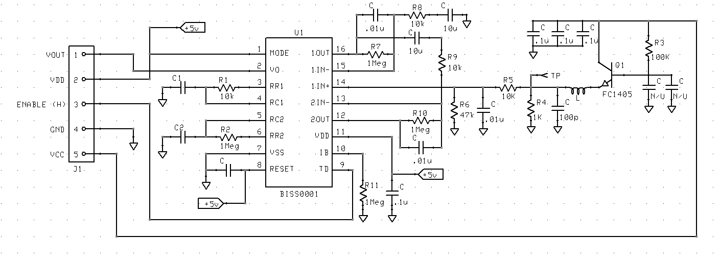
To understand what is going on the 2OUT I got my arduino and connected 2OUT to an analog input via 1megohm resistor.
The following picture already shows my modified circuit.

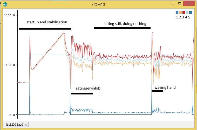
- startup and stabilization is .. fine .. this would explain the first long phase of the led staying high
- 2 = min value
- 3 = max value
- 4 = avg value (all during 50ms period)
- 1 = output value (aka LED)
- 5 = std-deviation (just for testing)
- scale 0-1023 is analogRead (aka 0-5V)
During the retrigger-inhib period the signal gets very eradic, even after replacing the amplification resistor (2nd Amplification stage) from 105 to a 150k (154). Before doing this the max signal would spike VH (0.7*VCC) and the output would instantly toggle again at the end of the inhibition period.. rendering the module useless.
EDIT: Try a variable resistor with maybe 200k Ohm to find the best value for your application
After replacing the amplification resistor I got the module working!
SOLUTION:
- Replace amplification resistor from 105 to eg. 154 (lowering the amplification) or put one in parallel
- (optional) Replace output pulse time resistor from 103 to 471 (10kohm 470ohm) (30sec -> 6 seconds)
- (optional) Lift pin 1 and connect to ground to prevent retriggering
Some additional ideas that worked very very well for me:
- Power the FC1816 VCC and UDP through an RC-Section (100Ohm Resistor and after that (on the side of the FC1816) an capacitory ~100-220µF)
My final solution I am currently using:
- Replace the 2nd stage-amplification resistor with a 150k
resistor
- Disable the trigger (PIN3 low) all together and grab the signal at 2OUT and feed it directly to an arduino for further processing
- Use a 150 ohms series resistor and after that an 1000µF cap. The 150 ohms are crucial .. i tried 80 ohms and this was way too low.
To do so I used the statistics library and had very good results with max/min/std-dev


