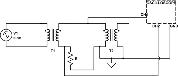
Consider the circuit with two trasformerstransformers in picture.

simulate this circuit – Schematic created using CircuitLab
I tried to simulate it and I get that on CH1 I see V1 traformedtransformed (i.e. V1 times the trasformationtransformation ratio of T1), while on CH2 I see approximately 0 Volts!
I tried for many values of R and V1 but the results it's always the same, nevertheless when I tried this on a real circuit I saw that both on CH1 and on CH2 I had nonzero sinusoidal voltage (and the difference between tensionvoltage was V1 times the trasformationtransformation ratio).
I do not understand why V on CH2 should be 0 volts at all.., can't current flow in the loop where R is placed? Is this related to the fact that the circuit is open after the second trasformertransformer?
