0
\$\begingroup\$

Consider the circuit with two transformers in picture.
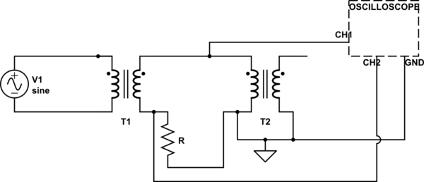
schematic

simulate this circuit – Schematic created using CircuitLab

I tried to simulate it and I get that on CH1 I see V1 transformed (i.e. V1 times the transformation ratio of T1), while on CH2 I see approximately 0 Volts!

I tried for many values of R and V1 but the results it's always the same, nevertheless when I tried this on a real circuit I saw that both on CH1 and on CH2 I had nonzero sinusoidal voltage (and the difference between voltage was V1 times the transformation ratio).

I do not understand why V on CH2 should be 0 volts at all.., can't current flow in the loop where R is placed? Is this related to the fact that the circuit is open after the second transformer?

\$\endgroup\$
4
  • \$\begingroup\$ The word you are translating as "tension" should probably actually be "voltage" or "potential". In English, "tension" is only used in a few set phrases from the early days of electrical technology (like "high tension line"). \$\endgroup\$
    – The Photon
    Commented Mar 23, 2017 at 16:34
  • \$\begingroup\$ Are these ideal transformers or do you expect some excitation current in the stored BH curve. \$\endgroup\$
    – D.A.S.
    Commented Mar 23, 2017 at 16:48
  • \$\begingroup\$ Put a load on the secondary of T2 to get some current flowing in your circuit. With ideal theoretical transformers there's no current flowing anywhere in your circuit, so no voltage drop across R. \$\endgroup\$
    – brhans
    Commented Mar 23, 2017 at 17:05
  • \$\begingroup\$ Don't feel sorry for tension. There really is a tension just like a rubber band and in BE, this was not an uncommon term for it in the past, like high tention line. Germanic laguages, Italian, Spanish and so on uses tension. In AE though, it's voltage due to their love of seeing physical quantities and units as the same thing. \$\endgroup\$
    – winny
    Commented Mar 23, 2017 at 18:14

1 Answer 1

0
\$\begingroup\$

Apply a load to the output of T2 while monitoring CH2 and you will then get a reading!

\$\endgroup\$
2
  • \$\begingroup\$ Care to elaborate? This does somewhat answer the question (and is perhaps better suited as a comment) but could use an explanation as to why current will flow through R2 which is what the OP asked for. \$\endgroup\$
    – Voltage Spike
    Commented Mar 23, 2017 at 18:53
  • \$\begingroup\$ Sorry about that, this is a lengthy explanation and may be a little clearer with this link and not my wording; electrical4u.com/… \$\endgroup\$
    – MEZLAW
    Commented Mar 23, 2017 at 20:19

Your Answer

By clicking “Post Your Answer”, you agree to our terms of service and acknowledge you have read our privacy policy.

Not the answer you're looking for? Browse other questions tagged or ask your own question.