Tweeted twitter.com/StackElectronix/status/870789611265589249
added 281 characters in body
Source Link

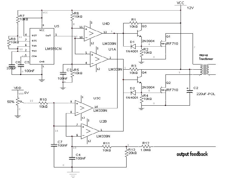
This is a circuit for switching the transformer at high frequency and so that we get ac on the secondary side. A voltage multiplier circuit is connected to the secondary of the transformer which will give a high voltage dc at the output. That dc voltage is then fedback which is shown in the figure as OUTPUT FEEDBACK. In this circuit i am not able to understand

  1. the use of 220microFarad capacitor which is connected with the centre tap of the transformer

  2. How is feedback circuit working, Is it a window comparator circuit?

  3. Use of transistor, I mean the Square wave which we are getting can be directly fed to the Mosfet but why have we used transistors?

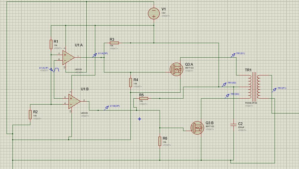
  4. I have uploaded a photo in reference to my 3rd question. I have simply removed transistors in this and i did its simulation in proteus and is working. I am unable to understand the use of transistor in this??new circuit

enter image description here

This is a circuit for switching the transformer at high frequency and so that we get ac on the secondary side. A voltage multiplier circuit is connected to the secondary of the transformer which will give a high voltage dc at the output. That dc voltage is then fedback which is shown in the figure as OUTPUT FEEDBACK. In this circuit i am not able to understand

  1. the use of 220microFarad capacitor which is connected with the centre tap of the transformer

  2. How is feedback circuit working, Is it a window comparator circuit?

  3. Use of transistor, I mean the Square wave which we are getting can be directly fed to the Mosfet but why have we used transistors?

  4. I have uploaded a photo in reference to my 3rd question. I have simply removed transistors in this and i did its simulation in proteus and is working. I am unable to understand the use of transistor in this??new circuit

enter image description here

improved formatting
Source Link
JRE
  • 73.6k
  • 10
  • 112
  • 195

This is a circuit for switching the transformer at high frequency and so that we get ac on the secondary side. A voltage multiplier circuit is connected to the secondary of the transformer which will give a high voltage dc at the output. That dc voltage is then fedback which is shown in the figure as OUTPUT FEEDBACK. In this circuit i am not able to understand

  1. the use of 220microFarad capacitor which is connected with the centre tap of the transformer

    the use of 220microFarad capacitor which is connected with the centre tap of the transformer

  2. How is feedback circuit working, Is it a window comparator circuit??

    How is feedback circuit working, Is it a window comparator circuit?

  3. Use of transistor, I mean the Square wave which we are getting can be directly fed to the Mosfet but why have we used transistors?enter image description here

    Use of transistor, I mean the Square wave which we are getting can be directly fed to the Mosfet but why have we used transistors?

enter image description here

This is a circuit for switching the transformer at high frequency and so that we get ac on the secondary side. A voltage multiplier circuit is connected to the secondary of the transformer which will give a high voltage dc at the output. That dc voltage is then fedback which is shown in the figure as OUTPUT FEEDBACK. In this circuit i am not able to understand

  1. the use of 220microFarad capacitor which is connected with the centre tap of the transformer
  2. How is feedback circuit working, Is it a window comparator circuit??
  3. Use of transistor, I mean the Square wave which we are getting can be directly fed to the Mosfet but why have we used transistors?enter image description here

This is a circuit for switching the transformer at high frequency and so that we get ac on the secondary side. A voltage multiplier circuit is connected to the secondary of the transformer which will give a high voltage dc at the output. That dc voltage is then fedback which is shown in the figure as OUTPUT FEEDBACK. In this circuit i am not able to understand

  1. the use of 220microFarad capacitor which is connected with the centre tap of the transformer

  2. How is feedback circuit working, Is it a window comparator circuit?

  3. Use of transistor, I mean the Square wave which we are getting can be directly fed to the Mosfet but why have we used transistors?

enter image description here

Source Link

Low voltage DC to High Voltage DC Circuit Explanation

This is a circuit for switching the transformer at high frequency and so that we get ac on the secondary side. A voltage multiplier circuit is connected to the secondary of the transformer which will give a high voltage dc at the output. That dc voltage is then fedback which is shown in the figure as OUTPUT FEEDBACK. In this circuit i am not able to understand

  1. the use of 220microFarad capacitor which is connected with the centre tap of the transformer
  2. How is feedback circuit working, Is it a window comparator circuit??
  3. Use of transistor, I mean the Square wave which we are getting can be directly fed to the Mosfet but why have we used transistors?enter image description here