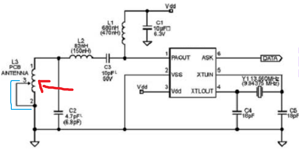
I'm attaching a schematic of an RF transmitter made by Synoxo http://www.synoxoSynoxo.com/ . Chip is SYN115. Schematicthe SYN115. The schematic is found onin the datasheet.
I do not understand why L3 which is the PCB antenna (pointed with the red arrow) is connected on both ends. As far as I know, antennas are connected on one end on a PCB and the other end is not connected anywhere. Also why there is no value to L3?
Also what is the black arrow (pointed with my blue line?)

