Added pics of top of the board and the triac.
Source Link

I have an apparently bizarre situation with a production pcb out of a Sprada coffee machine I am repairing. A BT136-600E TO-220 triac (NXP brand) is mounted the wrong way around on the pcb - pin1 (MT1)is swapped with pin3 (gate) ie. the triac has been rotated thru 180 degrees. Pin2 (MT2) is obviously as it should be. I deduce this because the datasheet show the pins as above but pin3 is directly connected to mains neutral on the pcb and pin1 is connected to a processor pin via a 270 ohm resistor. Pin2 is connected to the load, the load's other side to mains live.

The bizarre part is that the pcb silkscreen shows that the triac should be mounted this way, and this board has been manufactured and presumably tested this way. A second board I looked at is exactly the same so pcbs of this version and revision were presumably manufactured in bulk. The machine model is circa 2015 so the pcbs are not new. There is no evidence that the soldering has been disturbed ie. the triac has not been removed since manufacture. Since the triac drives an AC water pump there is no way that this could have been missed if it didnt work from day one. The fault on this board is that the triac has shorted pin1 to pin3. The water pump motor is rated at about 60W @ 230Vac (261mA) and the BT136 is a sensitive gate device which triggers at approximately 5mA.

So my only conclusions are that

  • a triac can operate when reversed, gate <-> MT1
  • there are versions of the BT136 triac that have pins 1 and 3 reversed
  • I've missed something obvious

I have not found any NXP/Philips/WeEn datasheets that point to the second possibility, so at the risk of making a clot of myself (3rd point) and going with the first one, my question is whether this is possible. How can the gate be triggered to conduct to MT2, and if so how much load current can it handle.

For this issue, I have done a bunch of research on the operation of triacs without finding a possible clue how triacs could operate in this configuration - perhaps I dont fully grasp the implications of gate vs MT1/MT2 currents and on/off states in the various quadrants. I have also used triacs in projects myself, but in a "conventional" configuration using MOCxxxx drivers.

If anyone could shed light on what could be happening I would be very grateful.

Edit: here are some pics Triac BT136 Topside

I have an apparently bizarre situation with a production pcb out of a Sprada coffee machine I am repairing. A BT136-600E TO-220 triac (NXP brand) is mounted the wrong way around on the pcb - pin1 (MT1)is swapped with pin3 (gate) ie. the triac has been rotated thru 180 degrees. Pin2 (MT2) is obviously as it should be. I deduce this because the datasheet show the pins as above but pin3 is directly connected to mains neutral on the pcb and pin1 is connected to a processor pin via a 270 ohm resistor. Pin2 is connected to the load, the load's other side to mains live.

The bizarre part is that the pcb silkscreen shows that the triac should be mounted this way, and this board has been manufactured and presumably tested this way. A second board I looked at is exactly the same so pcbs of this version and revision were presumably manufactured in bulk. The machine model is circa 2015 so the pcbs are not new. There is no evidence that the soldering has been disturbed ie. the triac has not been removed since manufacture. Since the triac drives an AC water pump there is no way that this could have been missed if it didnt work from day one. The fault on this board is that the triac has shorted pin1 to pin3. The water pump motor is rated at about 60W @ 230Vac (261mA) and the BT136 is a sensitive gate device which triggers at approximately 5mA.

So my only conclusions are that

  • a triac can operate when reversed, gate <-> MT1
  • there are versions of the BT136 triac that have pins 1 and 3 reversed
  • I've missed something obvious

I have not found any NXP/Philips/WeEn datasheets that point to the second possibility, so at the risk of making a clot of myself (3rd point) and going with the first one, my question is whether this is possible. How can the gate be triggered to conduct to MT2, and if so how much load current can it handle.

For this issue, I have done a bunch of research on the operation of triacs without finding a possible clue how triacs could operate in this configuration - perhaps I dont fully grasp the implications of gate vs MT1/MT2 currents and on/off states in the various quadrants. I have also used triacs in projects myself, but in a "conventional" configuration using MOCxxxx drivers.

If anyone could shed light on what could be happening I would be very grateful.
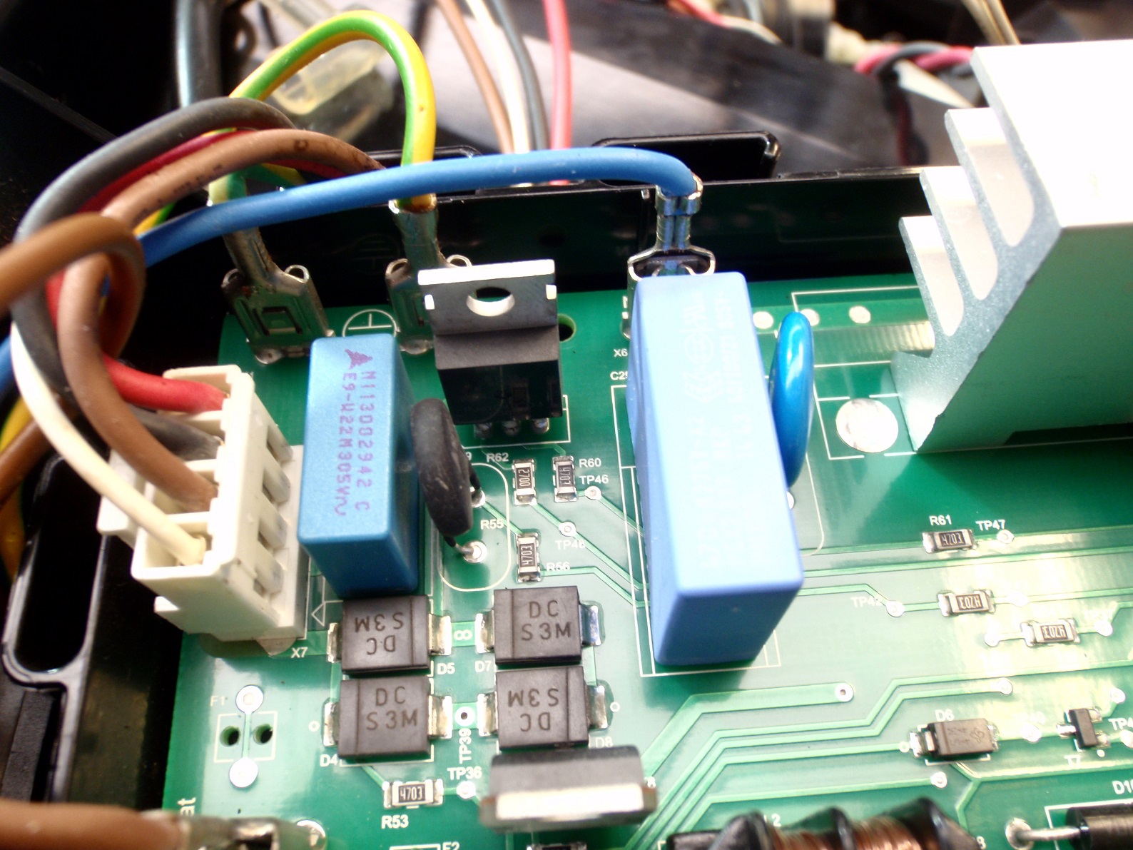
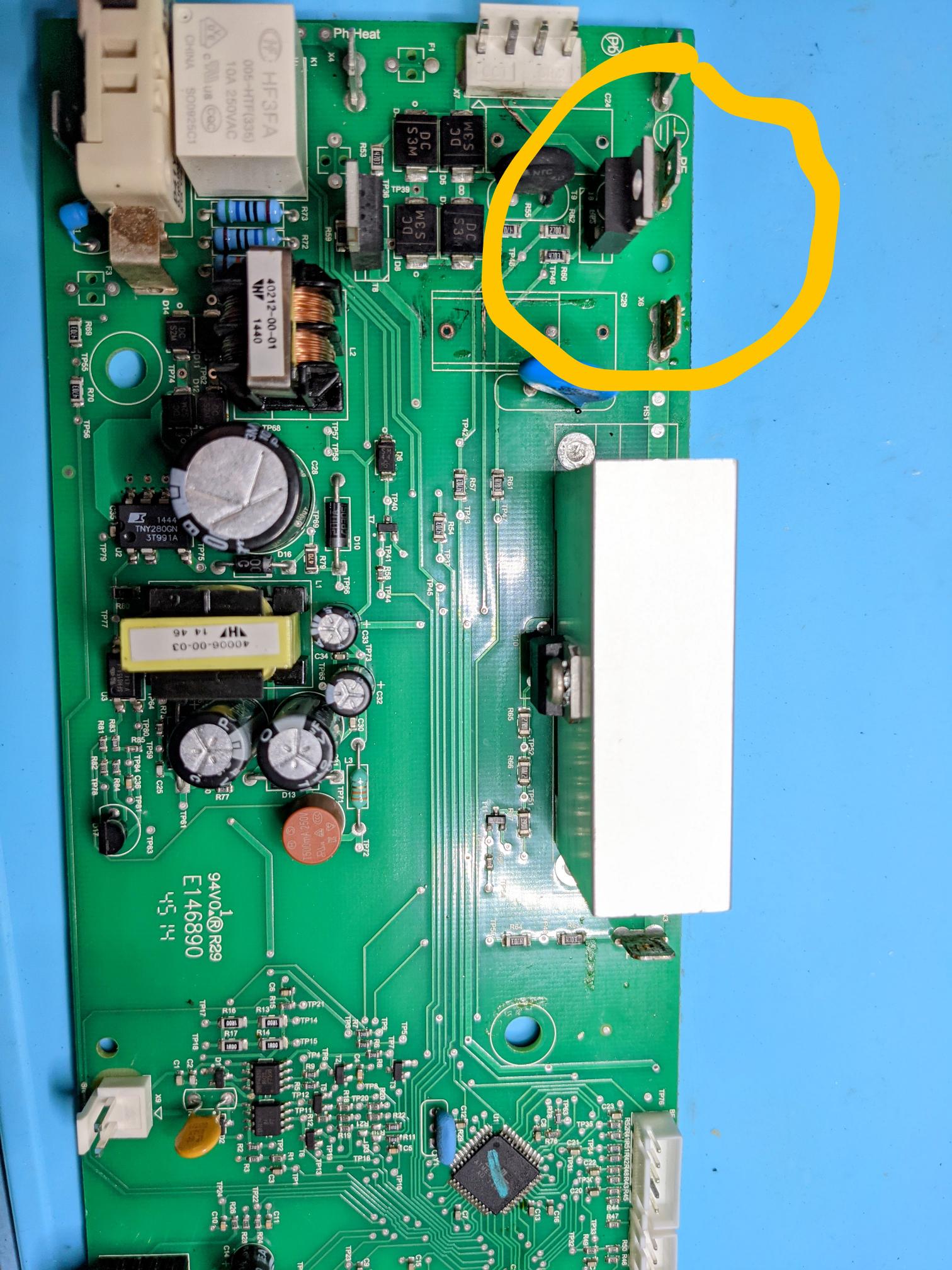
Edit: here are some pics Triac BT136 Topside

Source Link

Can a triac work with MT1 and gate reversed?

I have an apparently bizarre situation with a production pcb out of a Sprada coffee machine I am repairing. A BT136-600E TO-220 triac (NXP brand) is mounted the wrong way around on the pcb - pin1 (MT1)is swapped with pin3 (gate) ie. the triac has been rotated thru 180 degrees. Pin2 (MT2) is obviously as it should be. I deduce this because the datasheet show the pins as above but pin3 is directly connected to mains neutral on the pcb and pin1 is connected to a processor pin via a 270 ohm resistor. Pin2 is connected to the load, the load's other side to mains live.

The bizarre part is that the pcb silkscreen shows that the triac should be mounted this way, and this board has been manufactured and presumably tested this way. A second board I looked at is exactly the same so pcbs of this version and revision were presumably manufactured in bulk. The machine model is circa 2015 so the pcbs are not new. There is no evidence that the soldering has been disturbed ie. the triac has not been removed since manufacture. Since the triac drives an AC water pump there is no way that this could have been missed if it didnt work from day one. The fault on this board is that the triac has shorted pin1 to pin3. The water pump motor is rated at about 60W @ 230Vac (261mA) and the BT136 is a sensitive gate device which triggers at approximately 5mA.

So my only conclusions are that

  • a triac can operate when reversed, gate <-> MT1
  • there are versions of the BT136 triac that have pins 1 and 3 reversed
  • I've missed something obvious

I have not found any NXP/Philips/WeEn datasheets that point to the second possibility, so at the risk of making a clot of myself (3rd point) and going with the first one, my question is whether this is possible. How can the gate be triggered to conduct to MT2, and if so how much load current can it handle.

For this issue, I have done a bunch of research on the operation of triacs without finding a possible clue how triacs could operate in this configuration - perhaps I dont fully grasp the implications of gate vs MT1/MT2 currents and on/off states in the various quadrants. I have also used triacs in projects myself, but in a "conventional" configuration using MOCxxxx drivers.

If anyone could shed light on what could be happening I would be very grateful.