More about the "diode voltage source"
Source Link
Circuit fantasist
  • 19.5k
  • 2
  • 24
  • 71

As you can see, when V1 < V2, the "diode voltage source" can supply the input device:-)

As you can see, when V1 < V2, the "diode voltage source" can supply the input device:-)

Rearranging
Source Link
Circuit fantasist
  • 19.5k
  • 2
  • 24
  • 71

Current "source"

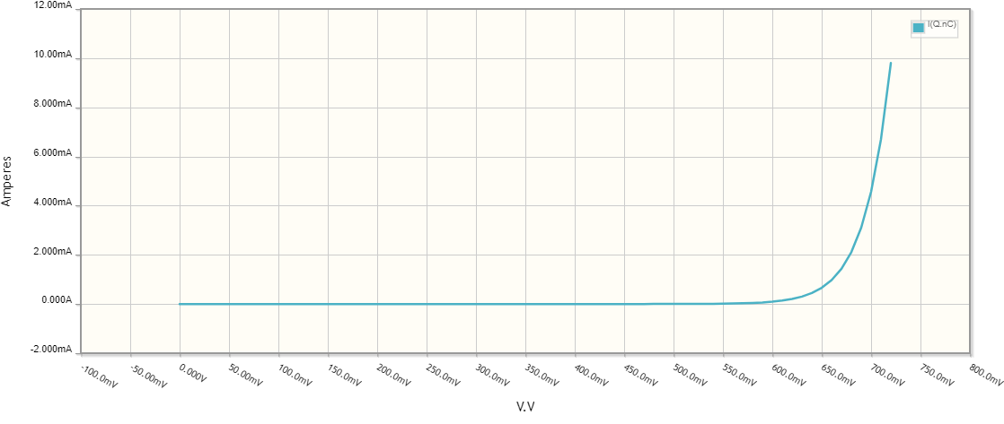
We can even make (model) a diode by a "dynamic" current source changing its current in the same way when the voltage varies. Here are the arrangements for the three typical points on the curve.

Point 0: VF = 425 mV; IF = 0 mA.
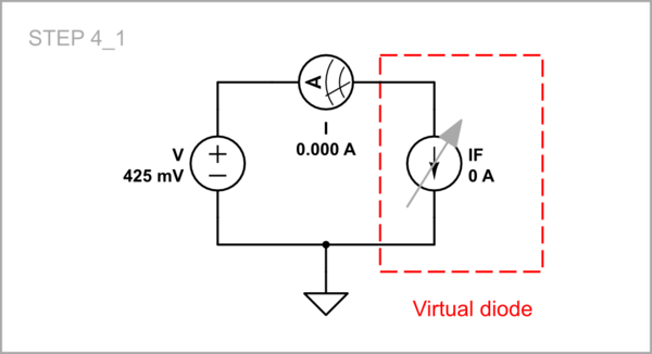
schematic

simulate this circuit

Point 1: VF = 644.3 mV, IF = 4 mA.
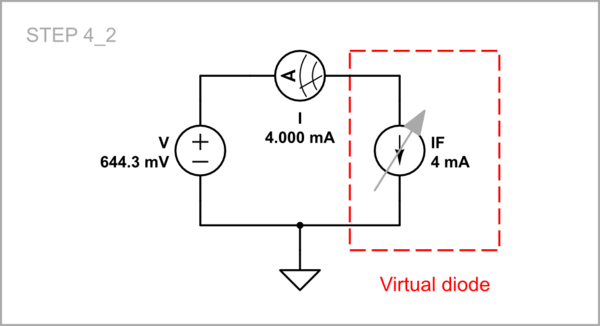
schematic

simulate this circuit

Point 2: VF = 678.4 mV, IF = 8 mA.
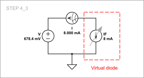
schematic

simulate this circuit

Implementation: "Active" diode

This idea is implemented in the so-called "active diode". As an example, let's make the schematic above this way.
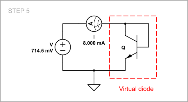
schematic

simulate this circuit

Here the transistor is a current "source" that adjusts its collector current so that to keep the respective voltage across itself.
STEP 5

See also my answer 1 and 2.

Added fun experiment
Source Link
Circuit fantasist
  • 19.5k
  • 2
  • 24
  • 71

Diode IV curve I = f(V)_6

As we can see as the voltage increases the resistance decreases and the IV curve is almost vertical.

Diode IV curve I = f(V)_6

Thus, if you continuously adjust the resistance for each value of the input voltage, you will mimic the real diode. If you hide in a box together with the resistor, the outside observer will think that there is a diode inside :-)

Diode IV curve I = f(V)_6

As we can see as the voltage increases the resistance decreases and the IV curve is almost vertical.

As we can see as the voltage increases the resistance decreases and the IV curve is almost vertical.

Diode IV curve I = f(V)_6

Thus, if you continuously adjust the resistance for each value of the input voltage, you will mimic the real diode. If you hide in a box together with the resistor, the outside observer will think that there is a diode inside :-)

Minor edit
Source Link
Circuit fantasist
  • 19.5k
  • 2
  • 24
  • 71
Loading
Source Link
Circuit fantasist
  • 19.5k
  • 2
  • 24
  • 71
Loading