deleted 131 characters in body; edited title
Source Link
JRE
  • 73.6k
  • 10
  • 112
  • 195

How does this zero crossing detector circuit works and modifyingwork? How can I modify it to work at lower supply voltage?

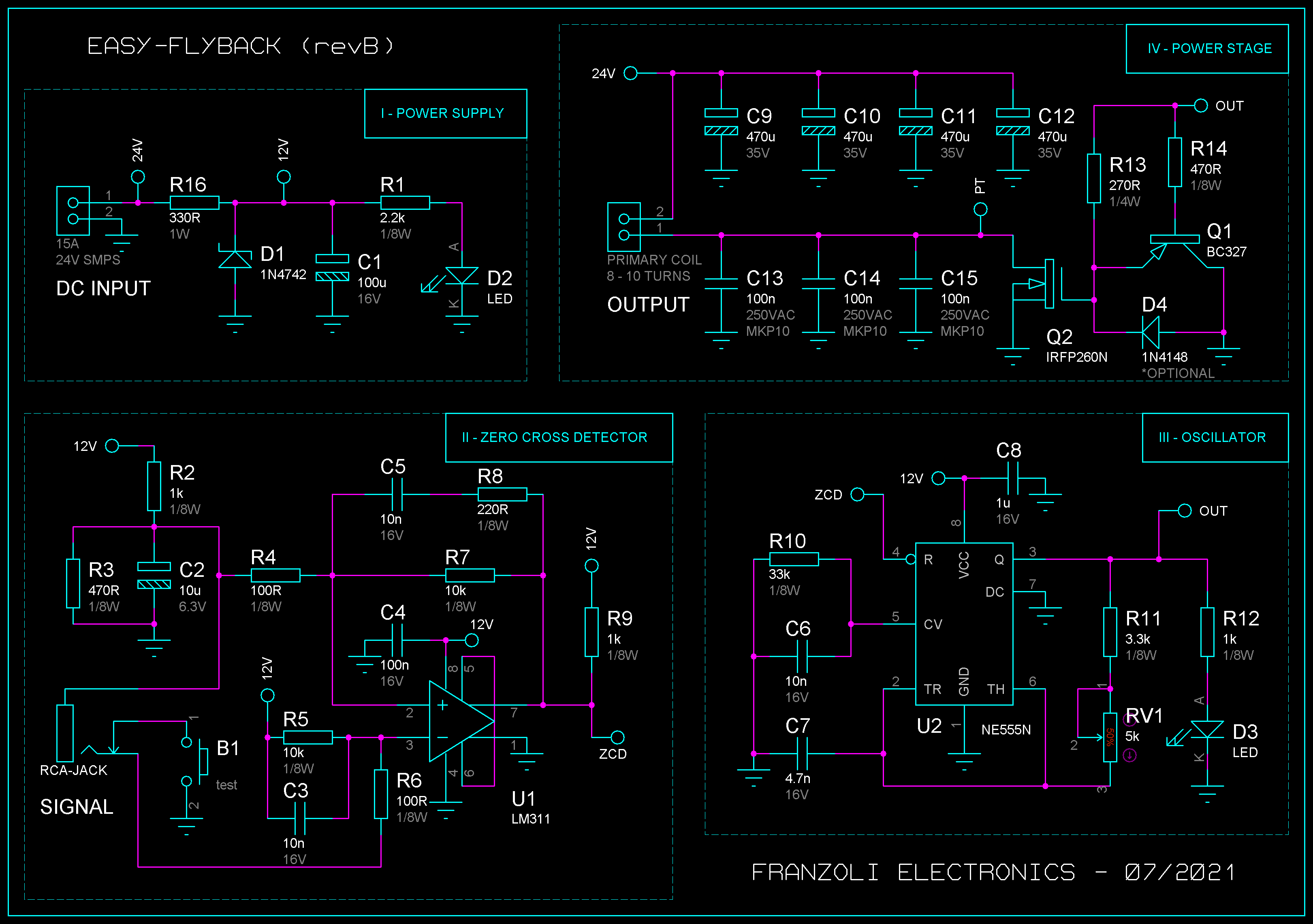
Recently I've been working on a zero crossing detector circuit for audio modulating a flyback transformer.

So far it's working great, but I have a few questions regarding the circuit and its operation.

schematic

Image source: Franzoli Electronics - Easy-Flyback I

Well my question is:

  1. What is the purpose of R2, R3, and R5 in the zero crossing detector section?

    What is the purpose of R2, R3, and R5 in the zero crossing detector section?
  2. Is it possible to use the zero crossing detector circuit at a lower voltage level, for example 5 V supply, and what components must be changed?

    Is it possible to use the zero crossing detector circuit at a lower voltage level, for example 5 V supply? What components must be changed?

My question might be elementary but your answers will be very helpful and useful for me.

How this zero crossing detector circuit works and modifying it to work at lower supply voltage

Recently I've been working on a zero crossing detector circuit for audio modulating a flyback transformer.

So far it's working great, but I have a few questions regarding the circuit and its operation.

schematic

Image source: Franzoli Electronics - Easy-Flyback I

Well my question is:

  1. What is the purpose of R2, R3, and R5 in the zero crossing detector section?

  2. Is it possible to use the zero crossing detector circuit at a lower voltage level, for example 5 V supply, and what components must be changed?

My question might be elementary but your answers will be very helpful and useful for me.
How does this zero crossing detector circuit work? How can I modify it to work at lower supply voltage?

I've been working on a zero crossing detector circuit for audio modulating a flyback transformer.

So far it's working great, but I have a few questions regarding the circuit and its operation.

schematic

Image source: Franzoli Electronics - Easy-Flyback I

  1. What is the purpose of R2, R3, and R5 in the zero crossing detector section?
  2. Is it possible to use the zero crossing detector circuit at a lower voltage level, for example 5 V supply? What components must be changed?
edited title
Link

Designing a How this zero crossing detector circuit for lowworks and modifying it to work at lower supply voltage output

Added link to (my best belief of) the source of the included content copied from elsewhere. The post's author is required to include source links for copied content, as explained in site rule: https://electronics.stackexchange.com/help/referencing
Source Link
SamGibson
  • 18.3k
  • 5
  • 41
  • 63

recentlyRecently I've been working on a zero crossing detector circuit for audio modulating a flyback transformer.

So far it's working great, but I have a few questions regarding the circuit and its operation.

enter image description hereschematic

The schematic is from Franzoli electronicsImage source: Franzoli Electronics - Easy-Flyback I

Well my question is:

  1. What is the purpose of R2, R3, and R5 in the zero crossing detector section?

  2. Is it possible to use the zero crossing detector circuit at a lower voltage level, for example 5 V supply, and what components must be changed?

My question might be elementary but your answers will be very helpful and useful for me.

recently I've been working on a zero crossing detector circuit for audio modulating a flyback transformer.

So far it's working great, but I have a few questions regarding the circuit and its operation.

enter image description here

The schematic is from Franzoli electronics

Well my question is:

  1. What is the purpose of R2, R3, and R5 in the zero crossing detector section?

  2. Is it possible to use the zero crossing detector circuit at a lower voltage level, for example 5 V supply, and what components must be changed?

My question might be elementary but your answers will be very helpful and useful for me.

Recently I've been working on a zero crossing detector circuit for audio modulating a flyback transformer.

So far it's working great, but I have a few questions regarding the circuit and its operation.

schematic

Image source: Franzoli Electronics - Easy-Flyback I

Well my question is:

  1. What is the purpose of R2, R3, and R5 in the zero crossing detector section?

  2. Is it possible to use the zero crossing detector circuit at a lower voltage level, for example 5 V supply, and what components must be changed?

My question might be elementary but your answers will be very helpful and useful for me.

Spelling, formatting, capitalization, grammar, its vs it's, and removed unnecessary thanks (show thanks by voting on and accepting answers).
Source Link
JYelton
  • 34.9k
  • 34
  • 147
  • 272
Loading
Source Link
Loading