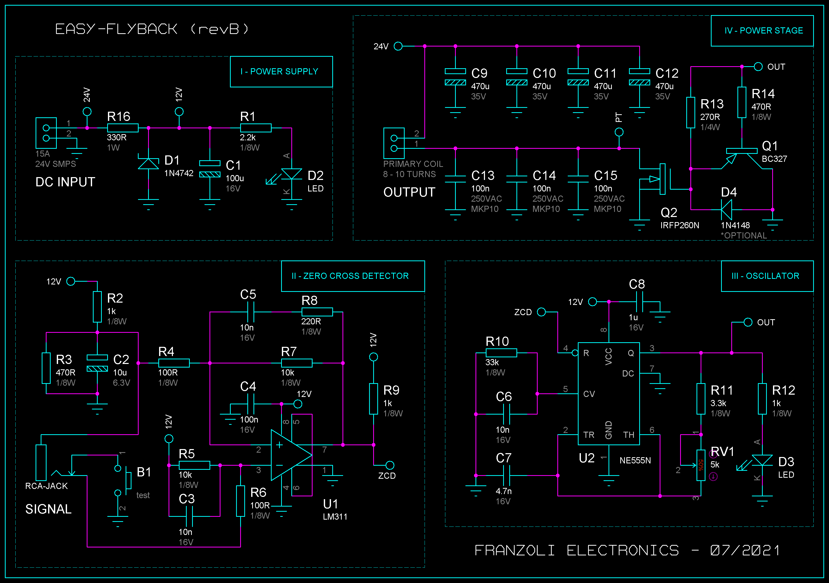
I've been working on a zero crossing detector circuit for audio modulating a flyback transformer.
So far it's working great, but I have a few questions regarding the circuit and its operation.
Image source: Franzoli Electronics - Easy-Flyback I
- What is the purpose of R2, R3, and R5 in the zero crossing detector section?
- Is it possible to use the zero crossing detector circuit at a lower voltage level, for example 5 V supply? What components must be changed?

