1
\$\begingroup\$

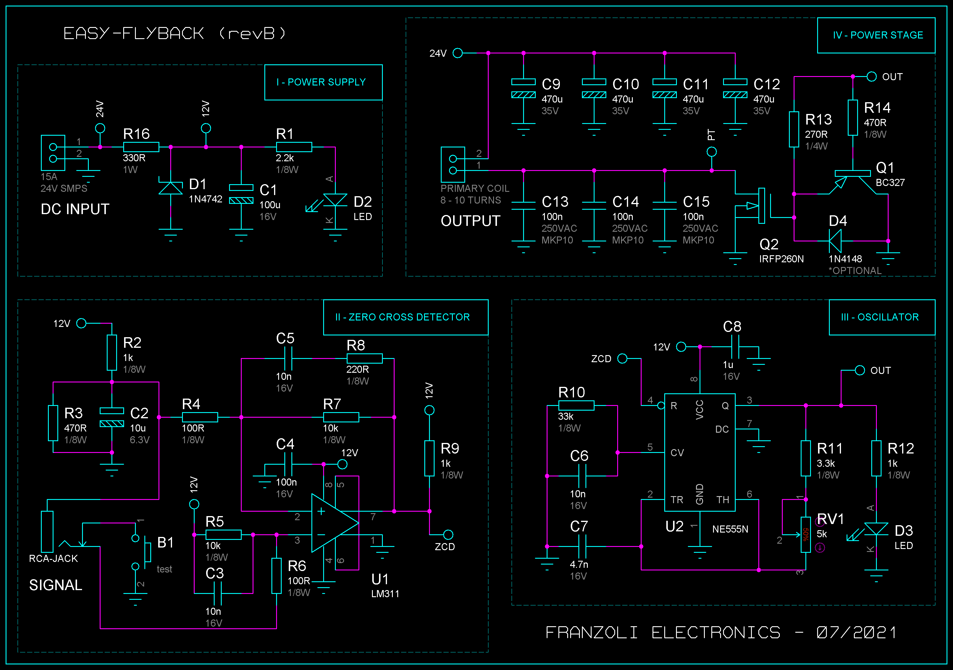
I've been working on a zero crossing detector circuit for audio modulating a flyback transformer.

So far it's working great, but I have a few questions regarding the circuit and its operation.

schematic

Image source: Franzoli Electronics - Easy-Flyback I

  1. What is the purpose of R2, R3, and R5 in the zero crossing detector section?
  2. Is it possible to use the zero crossing detector circuit at a lower voltage level, for example 5 V supply? What components must be changed?
\$\endgroup\$
3
  • \$\begingroup\$ those are all resistor dividers. as long as you produce the same output voltage you can fiddle with the input, numerators, and denominators. \$\endgroup\$
    – dandavis
    Commented Nov 3, 2023 at 19:35
  • \$\begingroup\$ actually, a lot of opamps don't like to be supplied single-sided with 5v, or at least you severally limit the range by doing so. \$\endgroup\$
    – dandavis
    Commented Nov 3, 2023 at 19:56
  • \$\begingroup\$ Perhaps 9v should be alright right? And why there is a resistive divider connected to the ground of the audio jack ? \$\endgroup\$ Commented Nov 4, 2023 at 1:11

2 Answers 2

1
\$\begingroup\$
  1. What is the purpose of R2, R3, and R5 in the zero crossing detector section?

R2 & R3 form a voltage divider from the +12V supply, which sets the threshold voltage for the comparator U1 pin 2. With the resistor values shown in the schematic, the voltage on C2 will be about 3.76V.

R5 pulls up the voltage at the inverting input of the comparator (U1 pin 3) to about +12V when there is no plug inserted at the RCA-JACK. In this case, the comparator (U1 pin 7) output will be low since V at +in is lower than the V at -in (U1 pin 2 is 3.7V, U1 pin 3 is +12V). If test switch B1 is pushed, then U1 pin 3 is pulled down to 0V via R6 (since R6 is only 100R compared to R5 at 10k), which causes the comparator output pin to change state to high impedance, causing U1 pin 7 to be pulled up to +12V via R9.

  1. Is it possible to use the zero crossing detector circuit at a lower voltage level, for example 5 V supply? What components must be changed?

The answer is: it depends. Which voltage are you referring to here, are you thinking of changing the +24V at the DC Input connector to +5V? Or just changing D1 to get 5V from the +24V? Or keeping the +12V and adding another voltage regulator to get +5V? Is this just for the Zero Cross Detector section, or do you want to change this voltage for the entire schematic including the Power Supply, Oscillator, and Power Stage?

If just for the ZCD stage, then the simplest approach without working through some circuit design would be to reduce all resistor values by a factor of 5/12, ie: multiply all values by 0.417, and select the nearest preferred value from that. Perhaps multiplying by 0.5 would be better. Leave the capacitor values unchanged.

If you want to convert the entire schematic to work from a +5V supply instead of a +12V supply then there will be significant changes required to all sections. The power section in particular will be more difficult since Q2 will have to change to a MOSFET that is fully ON when Vgs is just 5V rather than 12V - although these MOSFETs do exist, the range available is rather limited; MOSFETS that are fully ON at Vgs=12V are far more "standard".

\$\endgroup\$
1
  • 1
    \$\begingroup\$ Thank you very much for the information,this made things clear and i can move on further building the circuit \$\endgroup\$ Commented Nov 4, 2023 at 14:29
1
\$\begingroup\$

"1. What is the purpose of R2, R3, and R5 in the zero crossing detector section?"

As me, to make an appropriate voltage shift when input is not connected to jack. So ZCD will be in reasonable state in that situation. It also adds a little offset error when input is on.

"2. Is it possible to use the zero crossing detector circuit at a lower voltage level, for example 5 V supply?"

As me, there is not a problem with ZCD. But you'll have to alter the coil itself if coil voltage goes down to 5V too. And maybe take another output MOSFET, as 5V at gate may be not enough to completely open it.

The schematics looks robust, but antique and stuffed with parts.

\$\endgroup\$

Your Answer

By clicking “Post Your Answer”, you agree to our terms of service and acknowledge you have read our privacy policy.

Not the answer you're looking for? Browse other questions tagged or ask your own question.