Added link to a related answer
Source Link
Circuit fantasist
  • 19.5k
  • 2
  • 23
  • 71

I could writeSee also another story of mine dedicated to this dual story if there is interestcircuit phenomenon.

I could write this dual story if there is interest.

See also another story of mine dedicated to this circuit phenomenon.

Added more conclusions
Source Link
Circuit fantasist
  • 19.5k
  • 2
  • 23
  • 71

So this is not what OP need. They need:

  • a dynamic resistor that decreases its static (ohmic) resistance when the current through it increases.

  • It will be connected in series to an equivalent "positive" resistor so that to neutralize its resistance, and make the equivalent resistance zero.

I could write this dual story if there is interest.

Added explanations and a schematic
Source Link
Circuit fantasist
  • 19.5k
  • 2
  • 23
  • 71

Vin =1= 1 V, R-1k = 100 Ω: At 1 V input voltage, the 1 k positive resistor consumes 1 mA. The negative resistor has a 111 Ω resistance, so 9 mA current flows through it, and the total current consumed is 10 mA.

Vin =2= 2 V, R-1k = 222 Ω. When the input voltage increases to 2 V, the negative resistor increases its ohmic resistance to 250 Ω. Now the positive resistor consumes 2 mA but the negative 8 mA, and the total current consumed is again 10 mA (i.e., the left current increases but the right current decreases, and their sum I remains constant).

Vin =3= 3 V, R-1k = 375 Ω: Next, the input voltage increases to 3 V, and the negative resistor increases its ohmic resistance to 428 Ω. The positive resistor consumes 3 mA but the negative 7 mA, and the total current consumed is, as usual, 10 mA... and so on...

ApplicationApplications

I will illustrate my conceptual explanations above by solving a specific circuit problem - eliminating the impact of the load on the output voltage of a voltage divider.

Experimental setup

In the schematic below, a potentiometer P is loaded by a 1 kΩ "positive" resistor RL. A 1 kΩ (N-shaped) negative differential resistor R with initial resistance of 200 Ω is connected in parallel.

Vin = 5 V, R = 200 Ω: As a result, a total current I = 6 mA is consimed from the potentiometer output, and its output voltage is 1 V. Note that to simplify the schematic, I have implemented the resistors with "bad" ammeters having the same internal resistance (RL1k = 1 kΩ, R = 200 Ω).

Vin = 6 V, R = 333 Ω: When we increase Vin with 1 V, the potentiometer output voltage begins increasing. Simultaneously, the "negative" resistor R increases its resistance to 333 Ω thus compensating the influence of the positive load.
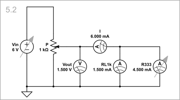
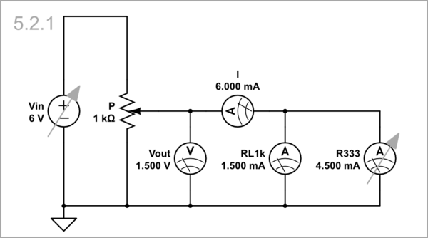
schematicschematic

simulate this circuitsimulate this circuit

As a result, the output voltage becomes 1.5 V instead of 1.2 V as it would be if R had not increased:
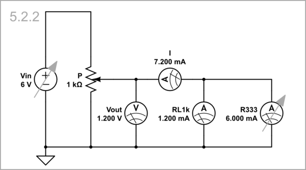
schematicschematic

simulate this circuitsimulate this circuit

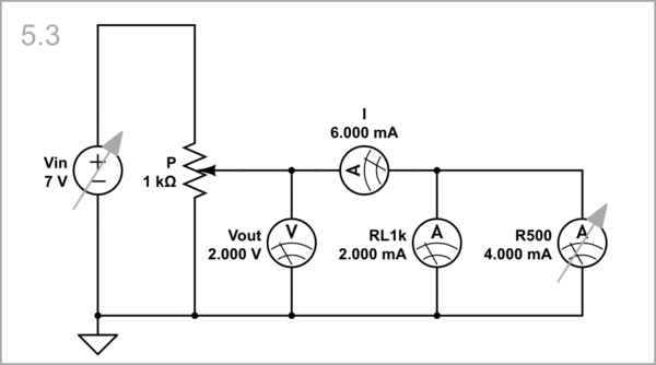
Vin = 7 V, R = 500 Ω: When we increase Vin by another 1 V, the potentiometer output voltage begins increasing even more. The "negative" resistor R increases its resistance to 500 Ω thus compensating the influence of the positive load.
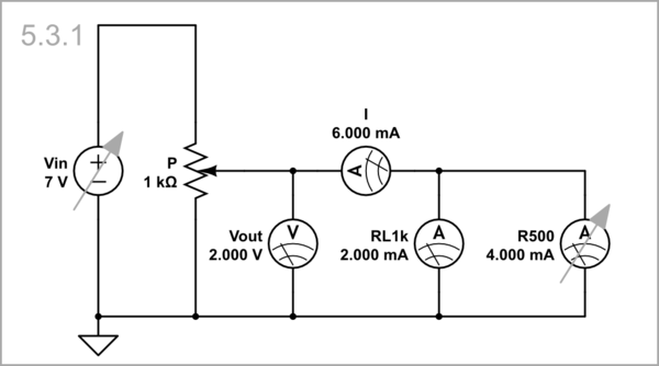
schematic

simulate this circuit

The output voltage becomes 2 V instead of 1.75 V as it would be if R had not increased:
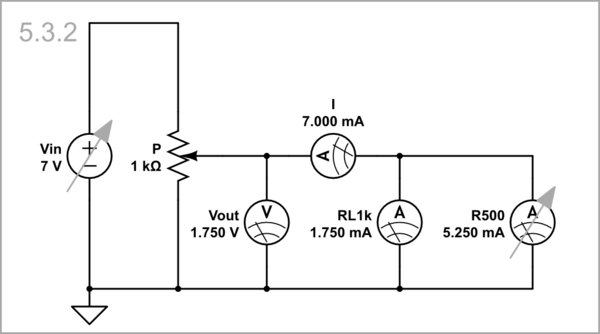
schematic

simulate this circuit

Equivalent circuit

So, the voltage divider is loaded with a 6 mA constant current source I, and the output voltage variations are not influenced by this extremely high-resistance load.

Vin =1 V, R-1k = 100 Ω: At 1 V input voltage, the 1 k positive resistor consumes 1 mA. The negative resistor has a 111 Ω resistance, so 9 mA current flows through it, and the total current consumed is 10 mA.

Vin =2 V, R-1k = 222 Ω. When the input voltage increases to 2 V, the negative resistor increases its ohmic resistance to 250 Ω. Now the positive resistor consumes 2 mA but the negative 8 mA, and the total current consumed is again 10 mA (i.e., the left current increases but the right current decreases, and their sum I remains constant).

Vin =3 V, R-1k = 375 Ω: Next, the input voltage increases to 3 V, and the negative resistor increases its ohmic resistance to 428 Ω. The positive resistor consumes 3 mA but the negative 7 mA, and the total current consumed is, as usual, 10 mA... and so on...

Application

schematic

simulate this circuit

schematic

simulate this circuit

Vin = 1 V, R-1k = 100 Ω: At 1 V input voltage, the 1 k positive resistor consumes 1 mA. The negative resistor has a 111 Ω resistance, so 9 mA current flows through it, and the total current consumed is 10 mA.

Vin = 2 V, R-1k = 222 Ω. When the input voltage increases to 2 V, the negative resistor increases its ohmic resistance to 250 Ω. Now the positive resistor consumes 2 mA but the negative 8 mA, and the total current consumed is again 10 mA (i.e., the left current increases but the right current decreases, and their sum I remains constant).

Vin = 3 V, R-1k = 375 Ω: Next, the input voltage increases to 3 V, and the negative resistor increases its ohmic resistance to 428 Ω. The positive resistor consumes 3 mA but the negative 7 mA, and the total current consumed is, as usual, 10 mA... and so on...

Applications

I will illustrate my conceptual explanations above by solving a specific circuit problem - eliminating the impact of the load on the output voltage of a voltage divider.

Experimental setup

In the schematic below, a potentiometer P is loaded by a 1 kΩ "positive" resistor RL. A 1 kΩ (N-shaped) negative differential resistor R with initial resistance of 200 Ω is connected in parallel.

Vin = 5 V, R = 200 Ω: As a result, a total current I = 6 mA is consimed from the potentiometer output, and its output voltage is 1 V. Note that to simplify the schematic, I have implemented the resistors with "bad" ammeters having the same internal resistance (RL1k = 1 kΩ, R = 200 Ω).

Vin = 6 V, R = 333 Ω: When we increase Vin with 1 V, the potentiometer output voltage begins increasing. Simultaneously, the "negative" resistor R increases its resistance to 333 Ω thus compensating the influence of the positive load.

schematic

simulate this circuit

As a result, the output voltage becomes 1.5 V instead of 1.2 V as it would be if R had not increased:

schematic

simulate this circuit

Vin = 7 V, R = 500 Ω: When we increase Vin by another 1 V, the potentiometer output voltage begins increasing even more. The "negative" resistor R increases its resistance to 500 Ω thus compensating the influence of the positive load.

schematic

simulate this circuit

The output voltage becomes 2 V instead of 1.75 V as it would be if R had not increased:

schematic

simulate this circuit

Equivalent circuit

So, the voltage divider is loaded with a 6 mA constant current source I, and the output voltage variations are not influenced by this extremely high-resistance load.

Source Link
Circuit fantasist
  • 19.5k
  • 2
  • 23
  • 71
Loading