Revealing the secret of negative differential resistance by CircuitLab experiments
Experimental setup
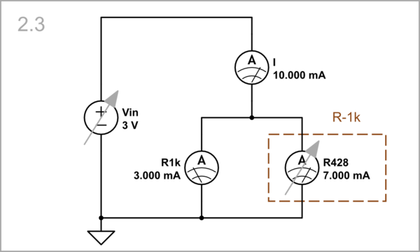
According to my comments above, two resistors are connected in parallel - R1k with a 1 kΩ "positive" resistance, and R-1k with a 1 kΩ "negative" resistance. I have put both names in square quotes because these resistances are neither negative nor positive, but the most common ohmic resistance known since the 19th century. So the negative differential resistance of -1 kΩ is implemented by a variable resistor whose resistance changes from 111 Ω to infinity when Vin varies from 1 V to 10 V.
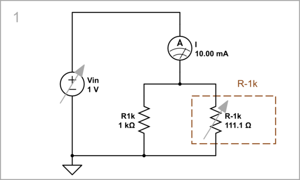
simulate this circuit – Schematic created using CircuitLab
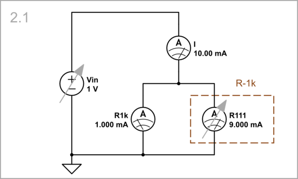
We need to observe the currents flowing through the resistors. To simplify the schematics, we can combine the resistors with the ammeters into one device ("visualized resistor"). To do this, open the parameters window of each of the two ammeters and set the corresponding internal resistance.
Step-by-step experiments
To understand the mechanism of this so-called "N-shaped negative differential resistance", let's first examine the circuit at three successive values of the input voltage - 1, 2 and 3 V.
Vin = 1 V, R-1k = 100 Ω: At 1 V input voltage, the 1 k positive resistor consumes 1 mA. The negative resistor has a 111 Ω resistance, so 9 mA current flows through it, and the total current consumed is 10 mA.
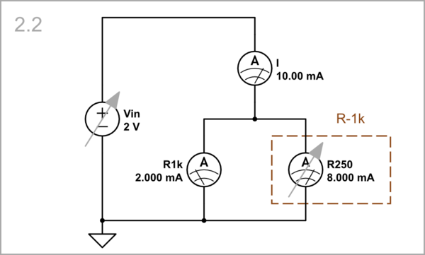
Vin = 2 V, R-1k = 222 Ω. When the input voltage increases to 2 V, the negative resistor increases its ohmic resistance to 250 Ω. Now the positive resistor consumes 2 mA but the negative 8 mA, and the total current consumed is again 10 mA (i.e., the left current increases but the right current decreases, and their sum I remains constant).
Vin = 3 V, R-1k = 375 Ω: Next, the input voltage increases to 3 V, and the negative resistor increases its ohmic resistance to 428 Ω. The positive resistor consumes 3 mA but the negative 7 mA, and the total current consumed is, as usual, 10 mA... and so on...
Automated experiment
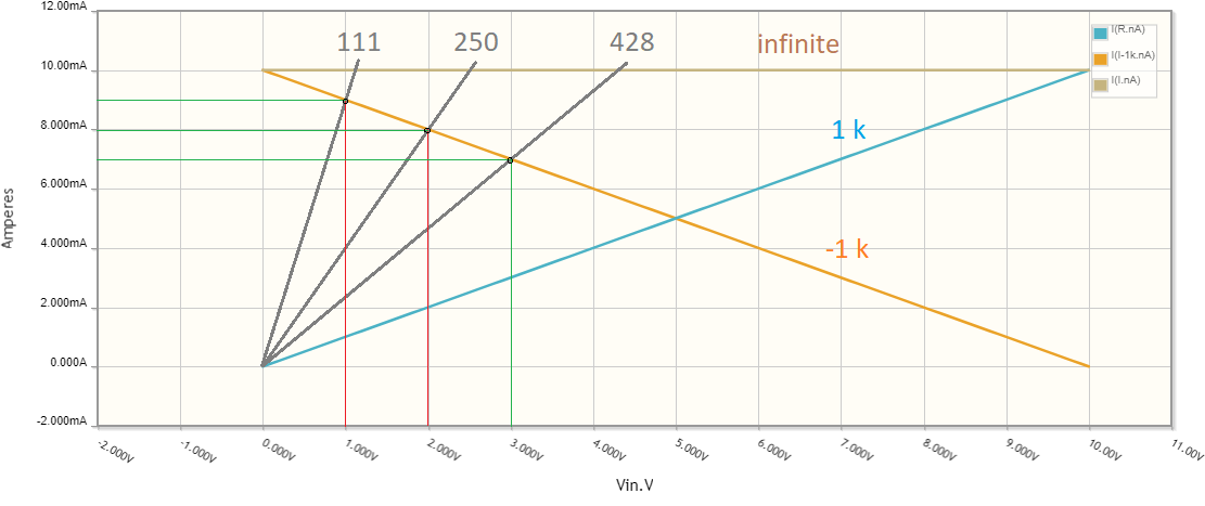
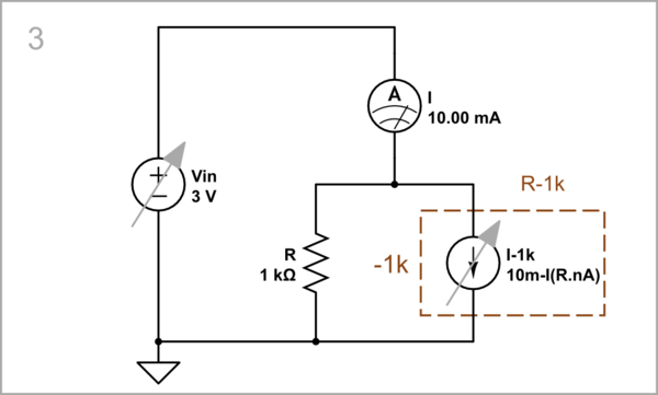
To sweep the negative resistance, we can simulate it using a behavioral current source I-1k that produces a current 10 mA - IR.
Graphical representation
From the graphs below, we see that as the input voltage increases, the current through the positive resistor increases and through the negative resistor decreases because its resistance increases. The result is a constant common current which is seen by the input voltage source as an infinite differential resistance.
Applications
I will illustrate my conceptual explanations above by solving a specific circuit problem - eliminating the impact of the load on the output voltage of a voltage divider.
Experimental setup
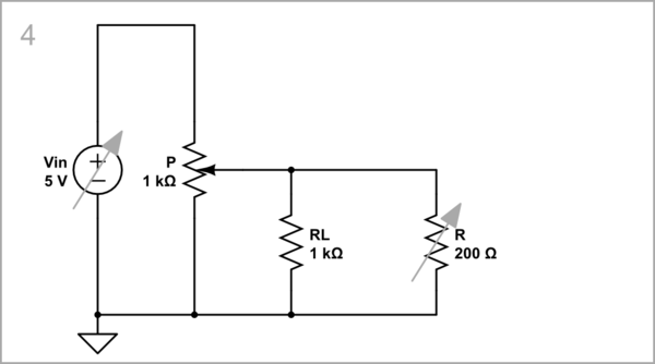
In the schematic below, a potentiometer P is loaded by a 1 kΩ "positive" resistor RL. A 1 kΩ (N-shaped) negative differential resistor R with initial resistance of 200 Ω is connected in parallel.
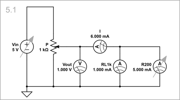
Vin = 5 V, R = 200 Ω: As a result, a total current I = 6 mA is consimed from the potentiometer output, and its output voltage is 1 V. Note that to simplify the schematic, I have implemented the resistors with "bad" ammeters having the same internal resistance (RL1k = 1 kΩ, R = 200 Ω).
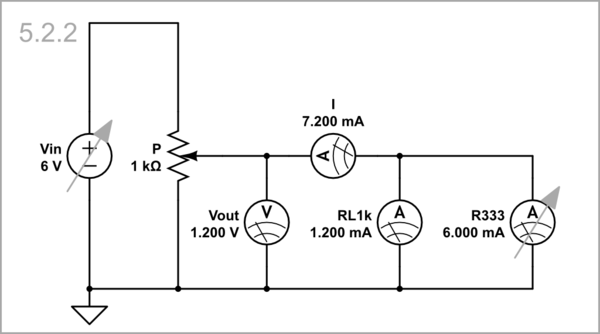
Vin = 6 V, R = 333 Ω: When we increase Vin with 1 V, the potentiometer output voltage begins increasing. Simultaneously, the "negative" resistor R increases its resistance to 333 Ω thus compensating the influence of the positive load.
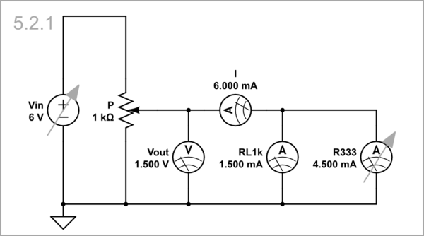
As a result, the output voltage becomes 1.5 V instead of 1.2 V as it would be if R had not increased:
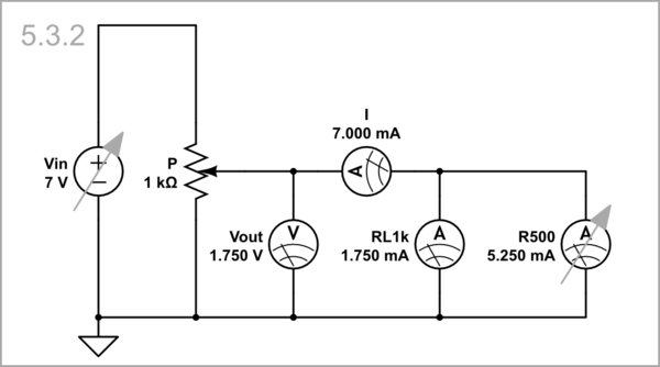
Vin = 7 V, R = 500 Ω: When we increase Vin by another 1 V, the potentiometer output voltage begins increasing even more. The "negative" resistor R increases its resistance to 500 Ω thus compensating the influence of the positive load.
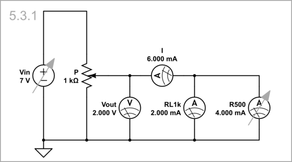
The output voltage becomes 2 V instead of 1.75 V as it would be if R had not increased:
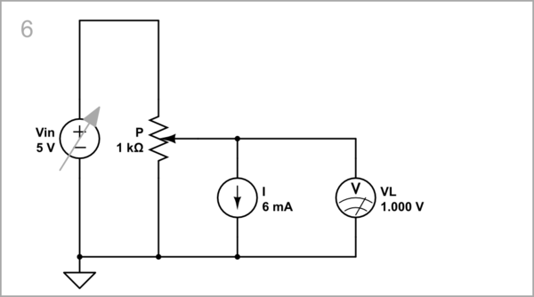
Equivalent circuit
So, the voltage divider is loaded with a 6 mA constant current source I, and the output voltage variations are not influenced by this extremely high-resistance load.
Conclusions
The N-shaped negative differential resistor (e.g. a tunnel diode) is a dynamic resistor that increases its static (ohmic) resistance when the voltage across it increases.
If connected in parallel to an equivalent "positive" resistor, it neutralizes its resistance so that the equivalent resistance is infinite.
So this is not what OP need. They need:
a dynamic resistor that decreases its static (ohmic) resistance when the current through it increases.
It will be connected in series to an equivalent "positive" resistor so that to neutralize its resistance, and make the equivalent resistance zero.
I could write this dual story if there is interest.

