added 18 characters in body
Source Link
Voltage Spike
  • 88.9k
  • 49
  • 90
  • 234

This is the first time I am making a high speed PCB so I am a bit unconfident. the ic I am talking about is this https://ftdichip.com/wp-content/uploads/2020/07/DS_FT2232H.pdf: FTDI232H

I have followed the schematic in the datasheet above and I have placed the capacitors and inductors close to the ic and I think I have given enough clearance to the traces.

I am planning to use a top layer polygon pour around the ic to make routing easier. Is this a better alternative to using vias?

edit: Should I just add an extra 1 or 2 layers and make one of them ground (just using 2 layers currently)?

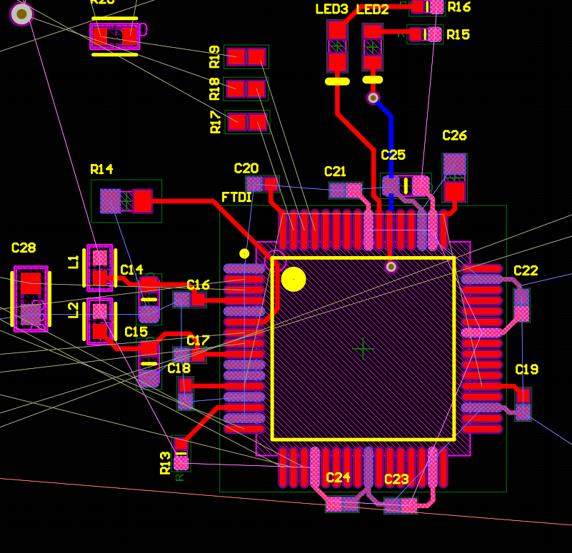
only using JTAG functionality and I have not forgotten oscillator and EEPROM

This is the first time I am making a high speed PCB so I am a bit unconfident. the ic I am talking about is this https://ftdichip.com/wp-content/uploads/2020/07/DS_FT2232H.pdf

I have followed the schematic in the datasheet above and I have placed the capacitors and inductors close to the ic and I think I have given enough clearance to the traces.

I am planning to use a top layer polygon pour around the ic to make routing easier. Is this a better alternative to using vias?

edit: Should I just add an extra 1 or 2 layers and make one of them ground (just using 2 layers currently)?

only using JTAG functionality and I have not forgotten oscillator and EEPROM

This is the first time I am making a high speed PCB so I am a bit unconfident. the ic I am talking about is this: FTDI232H

I have followed the schematic in the datasheet above and I have placed the capacitors and inductors close to the ic and I think I have given enough clearance to the traces.

I am planning to use a top layer polygon pour around the ic to make routing easier. Is this a better alternative to using vias?

edit: Should I just add an extra 1 or 2 layers and make one of them ground (just using 2 layers currently)?

only using JTAG functionality and I have not forgotten oscillator and EEPROM

added 32 characters in body
Source Link

This is the first time I am making a high speed PCB so I am a bit unconfident. the ic I am talking about is this https://ftdichip.com/wp-content/uploads/2020/07/DS_FT2232H.pdf

I have followed the schematic in the datasheet above and I have placed the capacitors and inductors close to the ic and I think I have given enough clearance to the traces.

I am planning to use a top layer polygon pour around the ic to make routing easier. Is this a better alternative to using vias?

edit: Should I just add an extra 1 or 2 layers and make one of them ground (just using 2 layers currently)?

only using JTAG functionality and I have not forgotten oscillator and EEPROM

This is the first time I am making a high speed PCB so I am a bit unconfident. the ic I am talking about is this https://ftdichip.com/wp-content/uploads/2020/07/DS_FT2232H.pdf

I have followed the schematic in the datasheet above and I have placed the capacitors and inductors close to the ic and I think I have given enough clearance to the traces.

I am planning to use a top layer polygon pour around the ic to make routing easier. Is this a better alternative to using vias?

edit: Should I just add an extra 1 or 2 layers and make one of them ground?

only using JTAG functionality and I have not forgotten oscillator and EEPROM

This is the first time I am making a high speed PCB so I am a bit unconfident. the ic I am talking about is this https://ftdichip.com/wp-content/uploads/2020/07/DS_FT2232H.pdf

I have followed the schematic in the datasheet above and I have placed the capacitors and inductors close to the ic and I think I have given enough clearance to the traces.

I am planning to use a top layer polygon pour around the ic to make routing easier. Is this a better alternative to using vias?

edit: Should I just add an extra 1 or 2 layers and make one of them ground (just using 2 layers currently)?

only using JTAG functionality and I have not forgotten oscillator and EEPROM

added 79 characters in body
Source Link

This is the first time I am making a high speed PCB so I am a bit unconfident. the ic I am talking about is this https://ftdichip.com/wp-content/uploads/2020/07/DS_FT2232H.pdf

I have followed the schematic in the datasheet above and I have placed the capacitors and inductors close to the ic and I think I have given enough clearance to the traces.

I am planning to use a top layer polygon pour around the ic to make routing easier. Is this a better alternative to using vias?

edit: Should I just add an extra 1 or 2 layers and make one of them ground?

only using JTAG functionality and I have not forgotten oscillator and EEPROM

This is the first time I am making a high speed PCB so I am a bit unconfident. the ic I am talking about is this https://ftdichip.com/wp-content/uploads/2020/07/DS_FT2232H.pdf

I have followed the schematic in the datasheet above and I have placed the capacitors and inductors close to the ic and I think I have given enough clearance to the traces.

I am planning to use a top layer polygon pour around the ic to make routing easier. Is this a better alternative to using vias?

edit: Should I just add an extra 1 or 2 layers and make one of them ground?

only using JTAG functionality and I have not forgotten oscillator and EEPROM

Source Link
Loading