From the capacitor characteristics database,
https://ds.murata.co.jp/simsurfing/mlcc.html?partnumbers=%5B%22GRM21BR61E226ME44%22%5D&oripartnumbers=%5B%22GRM21BR61E226ME44K%22%5D&rgear=jomoqke&rgearinfo=com&md5=1715917607821
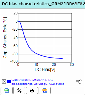
At a nominal input of 12V, these "22uF" caps are already a paltry 3.9uF each. In this regime, capacitance goes roughly inverse with voltage, so if the voltage doubles to 24V, capacitance falls to 2uF, etc.
If we input such a characteristic to an LC circuit, formed by the inductance of the power supply cable, and apply a transient equivalent to hot-plugging it, we find a peak voltage not just twice the applied voltage (which is the case for a constant-C capacitance), but many times higher still.
For example, here is a simulation demonstrating a dependent capacitor whose value is inverse with applied voltage, beyond some margin.
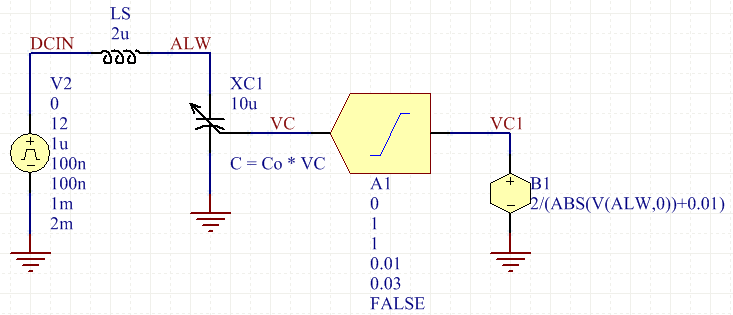
This uses a non-linear dependent (function) source, XSPICE LIMITER block, and a variable capacitor of my own design (links to my website) to approximate the situation in question.
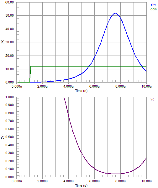
Notice the peak is 52V, far beyond the expected (linear case) 24V, and well beyond the nominal 12V input.
The linear case is already a surprise for those expecting to use, say, 18V-max devices on a 12V supply, but this behavior makes things so many times worse, still.
Some loss is required to constrain the peak. This can be done by clamping it directly, with a TVS, or providing a lossy "bulk" capacitor, typically electrolytic, whose ESR dominates and thus an overdamped response is obtained for most values of LS that might be connected.
As for LS, the inductance of wiring or cabling is on the order of 0.5uH per meter of length. This arises from the transmission line structure of a cable, and the low-frequency equivalent inductance of that transmission line.
(On a theoretical basis, we might envision the transient as myriad reflections back and forth on the transmission line, building up current flow as the line is highly mismatched at both ends -- there is a capacitor inside the power supply, and a capacitor at the inlet of your device, both having impedances very far from \$Z_0\$ of the cable. However, we aren't interested in the nanosecond-to-nanosecond history of this event, just the average behavior over some microseconds, so we invoke the lumped-equivalent approximation instead.)
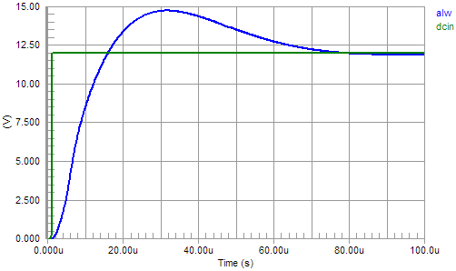
With damping or clamping,
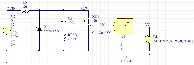
we see waveforms (damping dominant),
or clamping dominant (RESR = 1e6),
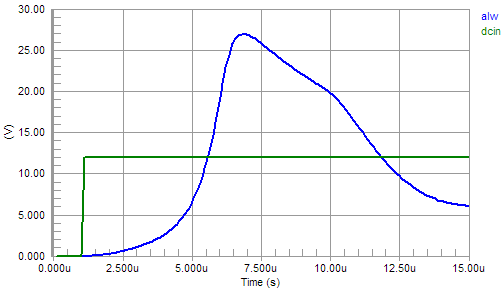
Damping is recommended in any case, to provide a positive and low impedance for the buck converter to operate into. Notice a buck converter has a negative incremental input resistance (current falls as voltage rises), so it can turn an LC resonant circuit into an oscillator.
This is not a complete answer, as without a datasheet, I cannot speak for the exact behavior your regulator is exhibiting, or what its ratings are, but this seems a likely prerequisite that must be solved before further evaluation can be performed.


