Tweeted twitter.com/#!/StackElectronix/status/389727704310112256
added 6 characters in body
Source Link
Aug
  • 1.6k
  • 7
  • 30
  • 65

I have a signal around 20 V peak-peak. I want to feed it into an emitter follower BJT and I have no experience in working with such large signals.

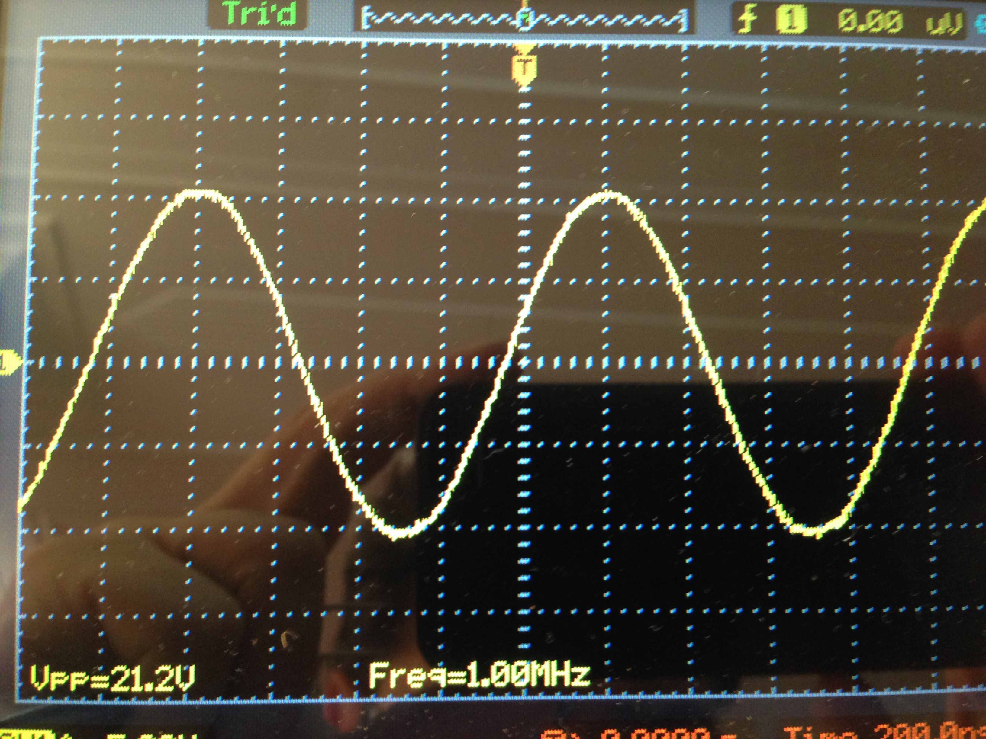
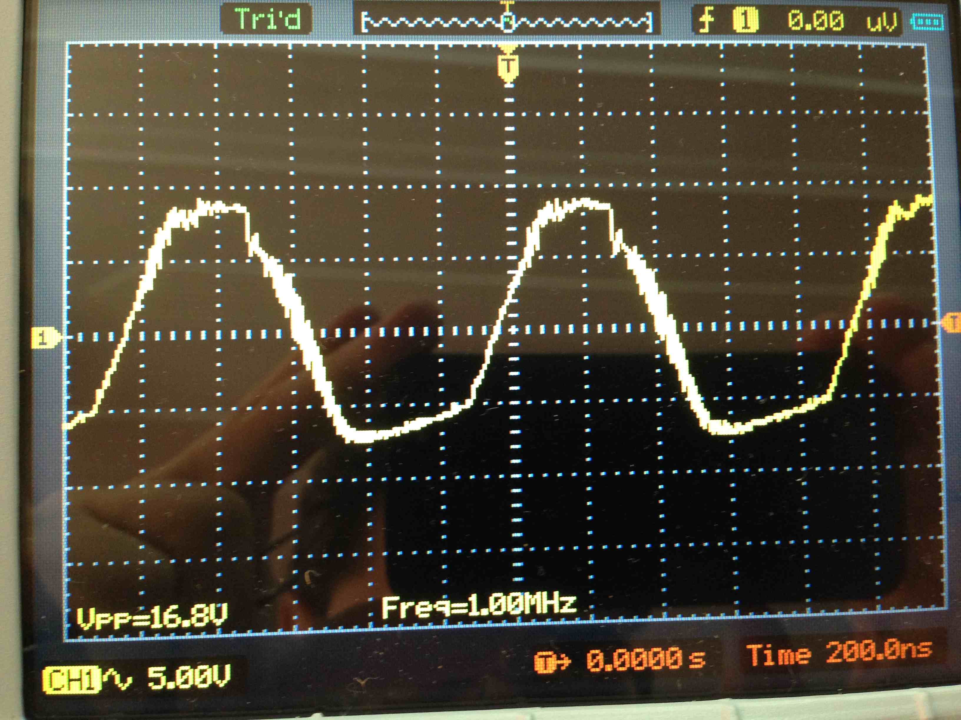
The BJT is well in bias point ( I tested the emitter DC voltage= 15 v with VCC=30V) , the result is awfully noisy and distorted. I included photo of input signal and the output. The frequency can be read on lower left corner of the photos and first issue is a voltage drop.

The second issue is the flat bottom of the output as if it is not well in bias point but it is well biased. I thought about the VCC but a VCC=30v should well handle a 21.2v signal ( at leats I think so).

For testing the bias point, I replaced the base resistor with a potentiometer . By turning the Pot, no better result found.

I tried many BJTs like 2N2219, BC108, BC109A , all the same result ( best result was with 2N2219). All are with moderate speed and transition frequency around 120-300MHz.

The frequency is not a main concern here as I tried many frequencies between 1Hz - 50MHz. Surprisingly the noise was far less in higher frequencies !!!

The design is not a complicated one, just a simple emitter follower (there is a typo, VCC is 30V ).

I put a photo of the input signal ( voltage can be read at left lower corner of the oscope screen and freq in the middle) and a photo of the result:

EDITION:EDITION: by reducing the input signal amplitude to 10vpp, everything goes well in low frequencies (<10MHz) but distortion gets worse in high frequencies. This may mean that the problem is with large signal size and I may need a faster BJT. How should I handle large signals?

1-Schematic ( VCC is 30 volts ) :
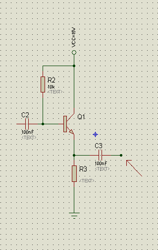
enter image description here

2-Input signal 21.2v 1MHz:

enter image description here

Output: enter image description here

I have a signal around 20 V peak-peak. I want to feed it into an emitter follower BJT and I have no experience in working with such large signals.

The BJT is well in bias point ( I tested the emitter DC voltage= 15 v with VCC=30V) , the result is awfully noisy and distorted. I included photo of input signal and the output. The frequency can be read on lower left corner of the photos and first issue is a voltage drop.

The second issue is the flat bottom of the output as if it is not well in bias point but it is well biased. I thought about the VCC but a VCC=30v should well handle a 21.2v signal ( at leats I think so).

For testing the bias point, I replaced the base resistor with a potentiometer . By turning the Pot, no better result found.

I tried many BJTs like 2N2219, BC108, BC109A , all the same result ( best result was with 2N2219). All are with moderate speed and transition frequency around 120-300MHz.

The frequency is not a main concern here as I tried many frequencies between 1Hz - 50MHz. Surprisingly the noise was far less in higher frequencies !!!

The design is not a complicated one, just a simple emitter follower (there is a typo, VCC is 30V ).

I put a photo of the input signal ( voltage can be read at left lower corner of the oscope screen and freq in the middle) and a photo of the result:

EDITION: by reducing the input signal amplitude to 10vpp, everything goes well in low frequencies (<10MHz) but distortion gets worse in high frequencies. This may mean that the problem is with large signal size and I may need a faster BJT. How should I handle large signals?

1-Schematic ( VCC is 30 volts ) :

enter image description here

2-Input signal 21.2v 1MHz:

enter image description here

Output: enter image description here

added 277 characters in body
Source Link
Aug
  • 1.6k
  • 7
  • 30
  • 65

I have a signal around 20 V peak-peak. I want to feed it into an emitter follower BJT and I have no experience in working with such large signals.

The BJT is well in bias point ( I tested the emitter DC voltage= 15 v with VCC=30V) , the result is awfully noisy and distorted. I included photo of input signal and the output. The frequency can be read on lower left corner of the photos and first issue is a voltage drop.

The second issue is the flat bottom of the output as if it is not well in bias point but it is well biased. I thought about the VCC but a VCC=30v should well handle a 21.2v signal ( at leats I think so).

For testing the bias point, I replaced the base resistor with a potentiometer . By turning the Pot, no better result found.

I tried many BJTs like 2N2219, BC108, BC109A , all the same result ( best result was with 2N2219). All are with moderate speed and transition frequency around 120-300MHz.

The frequency is not a main concern here as I tried many frequencies between 1Hz - 50MHz. Surprisingly the noise was far less in higher frequencies !!!

The design is not a complicated one, just a simple emitter follower (there is a typo, VCC is 30V ).

I put a photo of the input signal ( voltage can be read at left lower corner of the oscope screen and freq in the middle) and a photo of the result:

EDITION: by reducing the input signal amplitude to 10vpp, everything goes well in low frequencies (<10MHz) but distortion gets worse in high frequencies. This may mean that the problem is with large signal size and I may need a faster BJT. How should I handle large signals?

1-Schematic ( VCC is 30 volts ) :

enter image description here

2-Input signal 21.2v 1MHz:

enter image description here

Output: enter image description here

I have a signal around 20 V peak-peak. I want to feed it into an emitter follower BJT and I have no experience in working with such large signals.

The BJT is well in bias point ( I tested the emitter DC voltage= 15 v with VCC=30V) , the result is awfully noisy and distorted. I included photo of input signal and the output. The frequency can be read on lower left corner of the photos and first issue is a voltage drop.

The second issue is the flat bottom of the output as if it is not well in bias point but it is well biased. I thought about the VCC but a VCC=30v should well handle a 21.2v signal ( at leats I think so).

For testing the bias point, I replaced the base resistor with a potentiometer . By turning the Pot, no better result found.

I tried many BJTs like 2N2219, BC108, BC109A , all the same result ( best result was with 2N2219). All are with moderate speed and transition frequency around 120-300MHz.

The frequency is not a main concern here as I tried many frequencies between 1Hz - 50MHz. Surprisingly the noise was far less in higher frequencies !!!

The design is not a complicated one, just a simple emitter follower (there is a typo, VCC is 30V ).

I put a photo of the input signal ( voltage can be read at left lower corner of the oscope screen and freq in the middle) and a photo of the result:

EDITION: by reducing the input signal amplitude to 10vpp, everything goes well in low frequencies (<10MHz) but distortion gets worse in high frequencies. This may mean that the problem is with large signal size and I may need a faster BJT. How should I handle large signals?

1-Schematic ( VCC is 30 volts ) :

enter image description here

2-Input signal 21.2v 1MHz:

enter image description here

Output: enter image description here

Source Link
Aug
  • 1.6k
  • 7
  • 30
  • 65

Why emitter follower is so noisy and distorted in large signal?

I have a signal around 20 V peak-peak. I want to feed it into an emitter follower BJT and I have no experience in working with such large signals.

The BJT is well in bias point ( I tested the emitter DC voltage= 15 v with VCC=30V) , the result is awfully noisy and distorted. I included photo of input signal and the output. The frequency can be read on lower left corner of the photos and first issue is a voltage drop.

The second issue is the flat bottom of the output as if it is not well in bias point but it is well biased. I thought about the VCC but a VCC=30v should well handle a 21.2v signal ( at leats I think so).

For testing the bias point, I replaced the base resistor with a potentiometer . By turning the Pot, no better result found.

I tried many BJTs like 2N2219, BC108, BC109A , all the same result ( best result was with 2N2219). All are with moderate speed and transition frequency around 120-300MHz.

The frequency is not a main concern here as I tried many frequencies between 1Hz - 50MHz. Surprisingly the noise was far less in higher frequencies !!!

The design is not a complicated one, just a simple emitter follower (there is a typo, VCC is 30V ).

I put a photo of the input signal ( voltage can be read at left lower corner of the oscope screen and freq in the middle) and a photo of the result:

1-Schematic ( VCC is 30 volts ) :

enter image description here

2-Input signal 21.2v 1MHz:

enter image description here

Output: enter image description here