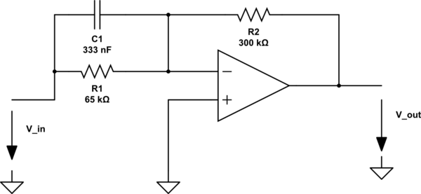
simulate this circuit – Schematic created using CircuitLab
I want to calculate the time constant τ of the filter. Can anybody help me?

simulate this circuit – Schematic created using CircuitLab
I want to calculate the time constant τ of the filter. Can anybody help me?
Looking at this circuit by considering its time constant is the right way to go. This is actually the basis for the fast analytical techniques or FACTs. In the considered circuit, set \$s=0\$ (open the capacitor) and determine the gain linking \$V_{in}\$ to \$V_{out}\$ as illustrated in sketch (b) below. Considering a perfect op-amp, the dc gain is immediate and equal to:
\$G_0=-\frac{R_2}{R_1}\$
To determine the time constant of this circuit, simply reduce the excitation to 0 and "look" at the resistance offered by \$C_1\$'s connecting terminals as shown in sketch (c). In this drawing, zeroing the excitation to 0 V is similar to replacing the source by a short circuit. In this mode, again considering a perfect op-amp, the left connection of \$C_1\$ is grounded while the right-one, considering the virtual ground, is also 0 V. The time constant is thus:
\$\tau=0\times C_1 = 0\$ implying that there is no pole in this circuit. Actually, there is one and it is coming from the op-amp but it is not set by the external components.
For the zero, what condition would imply that the stimulus would not propagate through the circuit to form a response at \$s=s_z\$? Well, if the parallel combination of \$C_1\$ and \$R_1\$ offers an infinite impedance, there is no response. An impedance becomes infinite when its denominator \$D(s)\$ equals zero. In other words, what is the pole of \$Z_1\$? It is the resistance \$R_1\$. The zero is located at:
\$\omega_z=\frac{1}{R_1C_1}\$ and our transfer function is:
\$G(s)=G_0(1+\frac{s}{\omega_z})\$
The Mathcad file is there: