0
\$\begingroup\$

The summing (usually inverting) amplifier is a classic op amp configuration. However, I'm struggling to find any products on the market which actually do this, leading me to conclude that I have to build my own.

The move from the textbook with its ideal components to the messy real world often comes with gotchas and problems you might not have thought of, and these practical considerations often end up dominating the noise budget of a system.

So: what kind of issues are there to be wary of when building a low noise, ~150 MHz, ~5dBm output, unity gain summing amplifier from parts? Or, alternatively, do commercial systems with these problems conveniently pre-solved exist?

Thanks in advance.

\$\endgroup\$
4
  • \$\begingroup\$ you might find low noise high impedance or an Op Amp with > 10GHz GBW add 50 Ohm R with 5dBm maybe.... There are > 10 thousand to choose from now depending on your cost performance specs since the uA741 and none of them may suit all your other specs like 3OI \$\endgroup\$
    – D.A.S.
    Commented May 2, 2019 at 23:16
  • 2
    \$\begingroup\$ It would help to know what problem you're actually trying to solve, so we can advise you whether an op-amp circuit is really the right way to go. \$\endgroup\$
    – The Photon
    Commented May 2, 2019 at 23:55
  • \$\begingroup\$ @The Photon good point. I need to combine two rf frequencies at ~100 and ~125 MHz. I'd prefer no nonlinearities, but could use a notch filter after the amplifier if necessary. This combined signal will then be sent to a power amplifier to produce a ~30 dBm drive. The most critical concern is that the frequencies are unaltered (and that the phase shift introduced is constant and, ideally, small) \$\endgroup\$
    – CharlieB
    Commented May 3, 2019 at 7:52
  • \$\begingroup\$ Cost per unit is not a concern: I only need one or two of these \$\endgroup\$
    – CharlieB
    Commented May 3, 2019 at 7:53

1 Answer 1

1
\$\begingroup\$

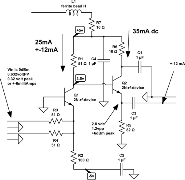
Since zero dBm is only 0.632 volts PeakPeak into 50 Ohms, you need 6dB higher at about 1.2 volts PP.

Consider this circuit

schematic

simulate this circuit – Schematic created using CircuitLab

The common-base summing node has about 1 ohm impedance (plus base inductance). There will be some small crosstalk between the 2 inputs. An opamp will, similarly, not be able to implement a zero-voltage virtual-ground (Vin-) at 150MHz.

The standard 2N3904 has very low beta at 150MHz (maybe 2). Try faster devices. Watch the power dissipation, and watch how the heat can exit the bipolars, and R2 and R5 pulldown.

\$\endgroup\$
2
  • \$\begingroup\$ Thanks for this, I'll have a look through to try to understand what's going on. \$\endgroup\$
    – CharlieB
    Commented May 7, 2019 at 9:48
  • 1
    \$\begingroup\$ Be respectful of the return path for input current. That path is: thru 51 ohm Rin, thru Q1 emitter, into R1 51 ohm to become the output voltage, and THEN back thru C4 to ground, and then OUT the ground side of the input RF connector of the original input. So you should place the GROUND node of C4 near the input connectors (2) Ground pins. \$\endgroup\$ Commented May 11, 2019 at 6:35

Your Answer

By clicking “Post Your Answer”, you agree to our terms of service and acknowledge you have read our privacy policy.

Not the answer you're looking for? Browse other questions tagged or ask your own question.