2
\$\begingroup\$

In my project I would like to switch between different resistors/capacitors on the fly, preferably without having to open the containing box around the PCB. Therefore, one idea was to use a jumper (connected via cables) which is placed on top of the box, which then can be used to set the currently active resistor/capacitor.
Are there other alternatives? I would prefer THT approaches, if possible.

The main aim of the circuit is to provide different R/C-constants for an OpAmp, operating at frequencies below 10 kHz. Switching between the different values should be as simple as possible, but still reliable, thus I prefer to avoid options mentioned like the alligator clips. Resistor values will be around 10k-10M, with voltages at +- 15V and currents < 1A. Cap values will be in the range of nF.

\$\endgroup\$
6
  • \$\begingroup\$ Surely you need to decide how professional you want this to be. The answer could range from a pair of wires with crocodile clips on to fasten the capacitor to, all the way through to a touch screen LCD where you drag and drop the components. \$\endgroup\$
    – HandyHowie
    Commented Oct 11, 2019 at 9:04
  • \$\begingroup\$ A simple, but reliable way. As mentioned, a jumper selecting fixed resistors was one alternative I thought of. A rotary switch which selects the resistor/capacitor another? I only have to switch through three/four different values anyway. \$\endgroup\$
    – arc_lupus
    Commented Oct 11, 2019 at 9:07
  • \$\begingroup\$ @arc_lupus A rotary switch may be fine. It is considered expensive today. If you get a chance to look at a very old TV, circa 1970s or earlier, take a look at the tuner control. It was often not much more than a way to select amongst various passives used in tuning. It was considered the height of commercial professional methods then. Jumpers work. You'd need to say a lot more about your application and values, though, and something about the distances involved in wiring things up. Those olden days tuners required a lot of careful layout considerations. \$\endgroup\$
    – jonk
    Commented Oct 11, 2019 at 9:41
  • \$\begingroup\$ @jonk: I added some more explanation about how I intend to use the switch in my layout. \$\endgroup\$
    – arc_lupus
    Commented Oct 11, 2019 at 11:24
  • \$\begingroup\$ @arc_lupus More detail might be helpful. Such as the exact schematic details surrounding the opamp under question. Single-ended vs differential switching matters, at least to some folks, for example. The nF range of cap values is a "nice to know" as that can then be compared to likely trace capacitances. The range of resistor values does pose a concern, as you near 10 M, for some approaches. Though it is probably just fine (usually) for a rotary switch arrangement. \$\endgroup\$
    – jonk
    Commented Oct 11, 2019 at 22:58

2 Answers 2

4
\$\begingroup\$

I am not so certain that there is a generic "best way" to choose between component selections. There may be a best way for your specific application and only you can determine what works for you. That said, there a multitude of ways that this can be done. Here are a few examples:

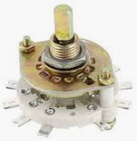
rotary switch

rotary switch

Picture Source

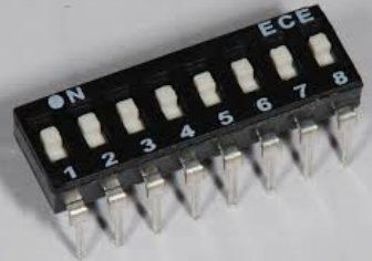
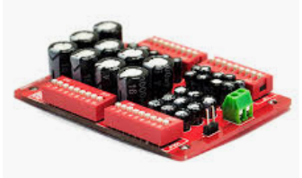
dip switch

dip switch

Picture Source

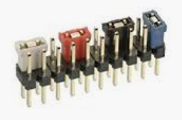
header with jumpers

header with jumpers

Picture Source

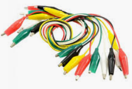
alligator clips

alligator clips

Picture Source

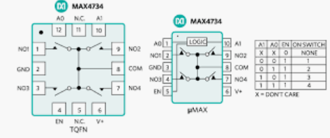
analog switch

analog switch

Picture Source

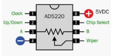
digipot

digipot

Picture Source

decade capacitor

decade capacitor

Picture Source

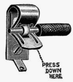
fahnestock clip

fahnestock clip

Picture Source

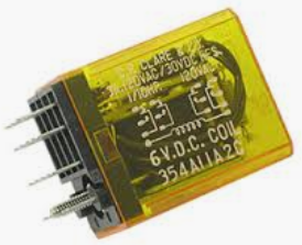
mechanical relay

enter image description here

Picture Source

soldering

soldering

Picture Source

\$\endgroup\$
4
  • \$\begingroup\$ This is giving a vague answer to a very vague question, Michael :-) \$\endgroup\$
    – TonyM
    Commented Oct 11, 2019 at 10:49
  • \$\begingroup\$ @TonyM - Is it less vague now? :^) \$\endgroup\$ Commented Oct 11, 2019 at 11:03
  • 2
    \$\begingroup\$ You forgot electromechanical relays. Since some of the resistance values are rather high, it calls for a solution that can provide high isolation. \$\endgroup\$
    – Dave Tweed
    Commented Oct 11, 2019 at 12:15
  • \$\begingroup\$ @DaveTweed - Added mechanical relay. \$\endgroup\$ Commented Oct 11, 2019 at 14:38
1
\$\begingroup\$

A simple female header or IC socket to insert THT components would do nicely and won't limit you to fixed set of values. Plus it costs just a fraction of other solutions. Also, if you have an old breadboard laying around you can use that, as is or cut a piece of it.

\$\endgroup\$

Your Answer

By clicking “Post Your Answer”, you agree to our terms of service and acknowledge you have read our privacy policy.

Not the answer you're looking for? Browse other questions tagged or ask your own question.