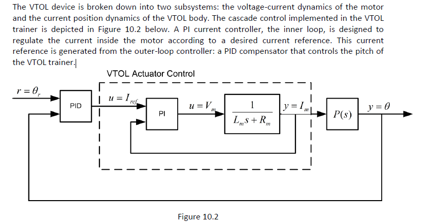
I was reading a manual about QNET VTOL and I came across a block diagram (shown in attached snapshot).
In the explaination of diagram, manual writes that
The VTOL device is broken down into two subsystems: the voltage-current dynamics of the motor and the current position dynamics of the VTOL body. The cascade control implemented in the VTOL trainer is depicted in Figure 10.2 below. A PI current controller, the inner loop, is designed to regulate the current inside the motor according to a desired current reference. This current reference is generated from the outer-loop controller: a PID compensator that controls the pitch of the VTOL trainer.
Where are the two subsytems in block diagram,i think one systems is motor represented by the one with denominator Lms+Rm,if yes how/where other system is represented?
After locating the two subsystems in block diagram, please also mention their working/aplication.

