0
\$\begingroup\$

I have 10 sensor units, each unit has 4 pin Vcc, Gnd, Digital out and analog out. enter image description here
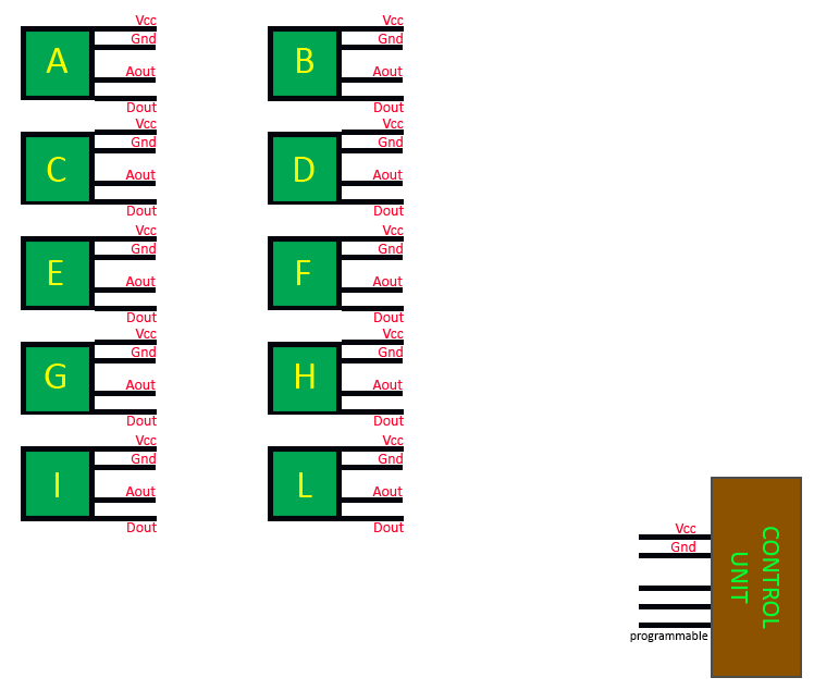
The main control unit that must receive the outputs has 2 pin for Vcc and Gnd and the others 3 pins are freely configurable for both digital and analog I\O operations.

I want to connect all the 10 sensor units at main control unit, but isn't strictly needed that the output of all the 10 units is received exactly at the same time (so eventually they could be alternated with some little delay each other).

How should I accomplish this?

Notes:

It's enough just analog output of each sensor for values, the digital isn't strictly needed

The output voltage of each sensor is in the range 0.1 - 5 Vc

\$\endgroup\$
4
  • \$\begingroup\$ Must the main controller receive the Aout as well as the Dout from each sensor? \$\endgroup\$
    – Huisman
    Commented Dec 14, 2019 at 21:35
  • \$\begingroup\$ @Huisman no, it's enough just analog output of each sensor \$\endgroup\$
    – AndreaF
    Commented Dec 14, 2019 at 21:41
  • \$\begingroup\$ what about digital only? \$\endgroup\$
    – jsotola
    Commented Dec 14, 2019 at 22:42
  • \$\begingroup\$ You need to specify the frequency and voltage range of the analog signals. \$\endgroup\$ Commented Dec 15, 2019 at 0:45

2 Answers 2

2
\$\begingroup\$

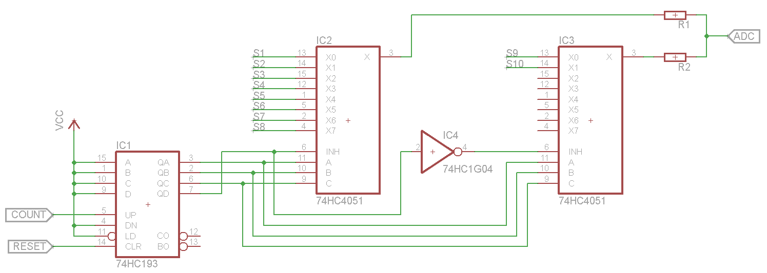
You can do this with only two chips: 16-channel analog mux with 4-bit binary address input (e.g. ADG706) and 4-bit binary counter with "clear" input (e.g. 74HCT393).

One control pin is used to reset counter to 0, another to increment counter (change mux address), and the last one is used as analog input from mux.

Update

Here is the schematics. I've used whatever symbols were available in the Eagle, so the pin names are different from those in the datasheets. But the pinouts are compatible, so it should be trivial to figure out. And, of course, you can use any level-compatible inverter/nand/nor chip for IC4. Something like 100R resistors should be sufficient to protect sensor outputs while not interfering much with ADC. Oh, and don't forget to connect Vee of the muxes to the ground. enter image description here

\$\endgroup\$
5
  • \$\begingroup\$ thanks for the answer. Could I use counter SN74LS93N and mux 74HC4051D? (my local store hasn't available the ones proposed) \$\endgroup\$
    – AndreaF
    Commented Dec 15, 2019 at 14:20
  • 1
    \$\begingroup\$ You can use that mux but you need two of them for 10 sensors since they have only 8 channels. You'd also need an inverter chip for one address line. You cannot use 74LS counter with 74HC mux because LS series has TTL levels and HC is CMOS. Look for the chips compatible with your control unit and each other. \$\endgroup\$
    – Maple
    Commented Dec 15, 2019 at 17:37
  • 1
    \$\begingroup\$ Also note, that using !EN input as additional address line removes break-before-make functionality between the muxes, which can potentially damage your sensors. You might need to add series resistors to mux outputs to deal with this. \$\endgroup\$
    – Maple
    Commented Dec 15, 2019 at 18:06
  • \$\begingroup\$ Thanks again! Could I use the counter 74HC193D with 2 mux 74HC4051D instead? Also could you add to the answer more details about the resistor configuration to avoid risk of sensor damages? \$\endgroup\$
    – AndreaF
    Commented Dec 15, 2019 at 22:37
  • 1
    \$\begingroup\$ Yes, you can use HC193 with HC4051. But make sure your "control unit", whatever that might be, has CMOS outputs. Or look for HCT193, which should be compatible with most MCUs. I'll add a schematics when I have time. Or you can draw one yourself and update OP, so that someone comment on it. \$\endgroup\$
    – Maple
    Commented Dec 15, 2019 at 23:38
0
\$\begingroup\$

You need to control the muxes but it seems your main control unit doesn't have spare pins to control the muxes.

Not sure whether the main controller has to receive the Aout as well as the Dout from each sensor. Either way, you have only 1 or 2 pins left which can select 2^1 or 2^2 sensors: too few spare pins.

So, you likely need another circuit to provide this selecting of sensors, e.g. a small uP or counter.
I'd connect each same labelled pin of each sensor to a mux (so, you got a Vcc mux, a Aout mux, a Dout mux, etc) so you can control these muxes with the same controlling bits.

You could use (one of) the spare pin on the main control unit for timing. Have it act as master to dictate when the counter/uP has to change the mux selection bits.

\$\endgroup\$
2
  • \$\begingroup\$ could you suggest me the component models that I could use respectively? \$\endgroup\$
    – AndreaF
    Commented Dec 14, 2019 at 22:27
  • \$\begingroup\$ Not by heart. I'd just search internet or distributor (Mouser, Farnell) for "analog multiplexer" \$\endgroup\$
    – Huisman
    Commented Dec 14, 2019 at 22:31

Your Answer

By clicking “Post Your Answer”, you agree to our terms of service and acknowledge you have read our privacy policy.

Not the answer you're looking for? Browse other questions tagged or ask your own question.