The aim of this modification is that the speaker system (Logitech Z903) is working with 12V input (don’t worry about the Amps).
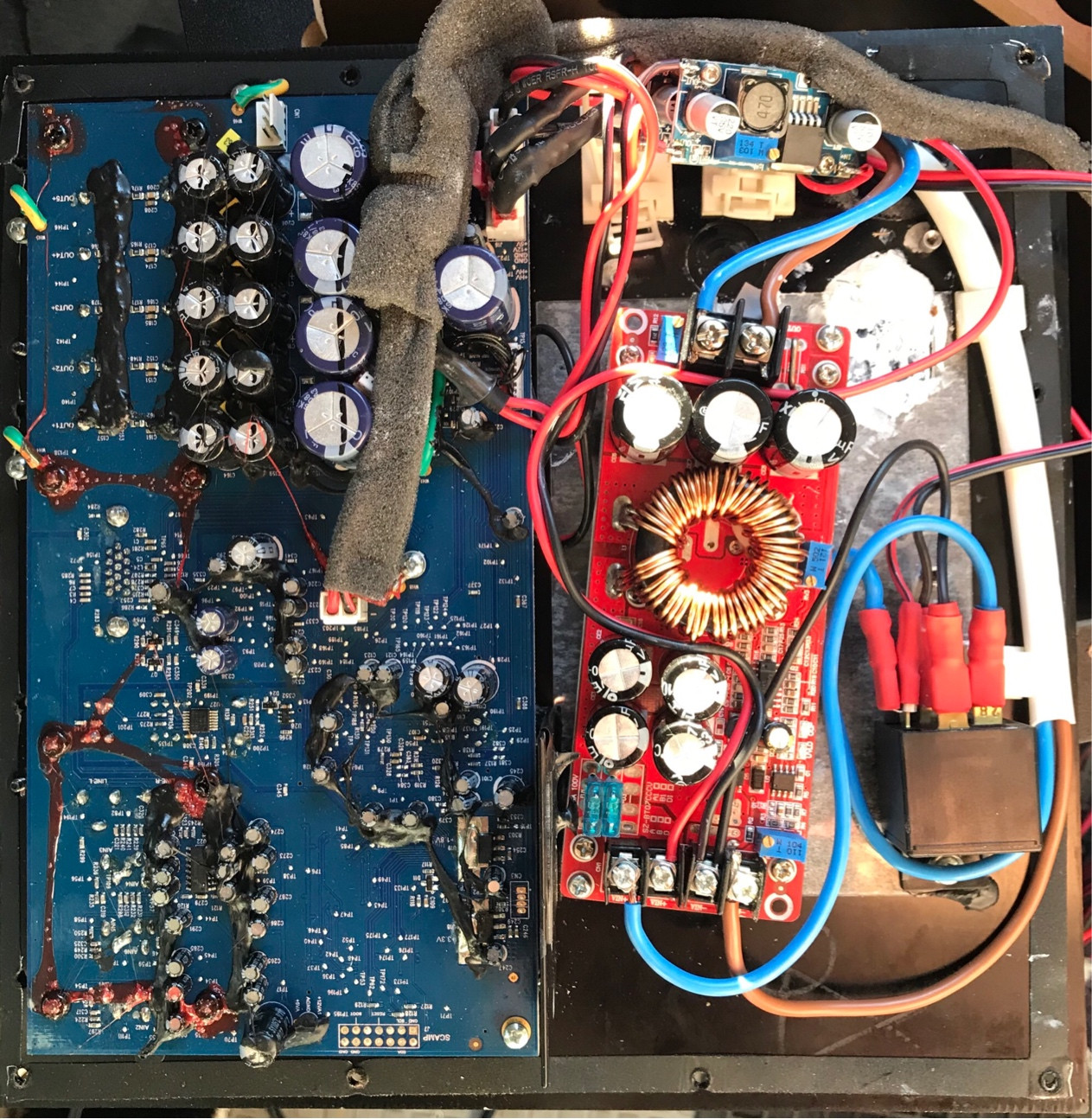
The power supply of my Loudspeakers has an Input of 220-250VAC @50Hz 550mA It transforms it to 45.5VDC, 12VDC and 5VDC. My plan is to use a non-branded chinese boost-converter to reach the 45.5V (like this) The only problem I face is that the original power-supply-PCB is connected to the main-PCB not only to share the power (1st picture).
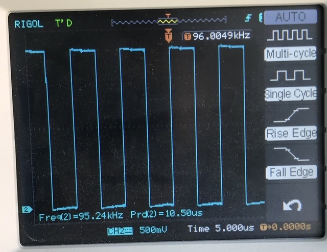
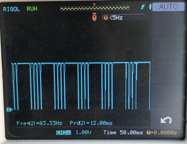
The other connector (8-pin) has the following Pin-names printed on the board (values measured by using an oscilloscope - with connected 8-pin-cable):
- TEMP3 (3rd picture 3.3VPeak, switch-off: 0V)
- TEMP RET (same as above)
- nPWR_OFF (5.4VDC, switch-off: 0V)
- GND
- PSSYNC2 (same as 2nd pic but 385kHz, switch-off: 0V)
- PSSYNC1 (2nd picture 3.3VPeak, switch-off: 0V)
- GND
- +3.3V KEEP ALIVE (3.3VDC always)
If I just pitch-off the 8-pin connector - the voltage supplied to the main-board remains the same, but the system cannot be switched-on anymore. Just wondering what I could do that the system runs without the 8-pin-cable connected to the original power-supply-pcb.
The “switch” is a button connected to the main-board.
Any hint is very much appreciated!


