0
\$\begingroup\$

The aim of this modification is that the speaker system (Logitech Z903) is working with 12V input (don’t worry about the Amps).

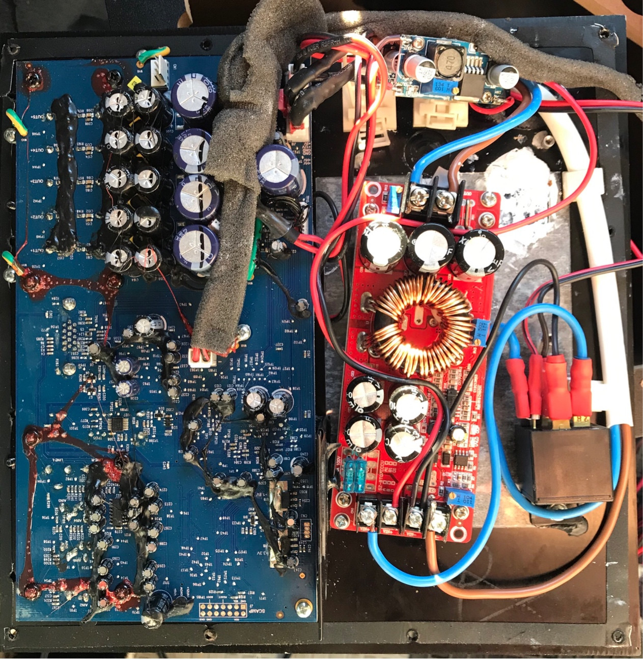
The power supply of my Loudspeakers has an Input of 220-250VAC @50Hz 550mA It transforms it to 45.5VDC, 12VDC and 5VDC. My plan is to use a non-branded chinese boost-converter to reach the 45.5V (like this) The only problem I face is that the original power-supply-PCB is connected to the main-PCB not only to share the power (1st picture).

The other connector (8-pin) has the following Pin-names printed on the board (values measured by using an oscilloscope - with connected 8-pin-cable):

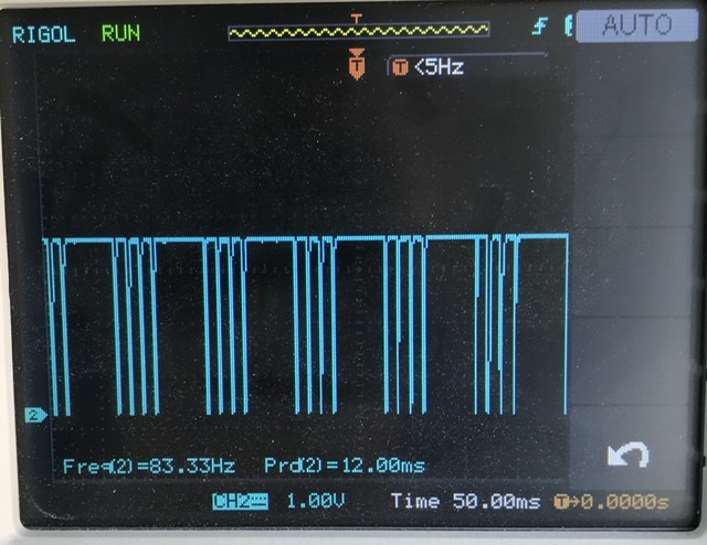
  • TEMP3 (3rd picture 3.3VPeak, switch-off: 0V)
  • TEMP RET (same as above)
  • nPWR_OFF (5.4VDC, switch-off: 0V)
  • GND
  • PSSYNC2 (same as 2nd pic but 385kHz, switch-off: 0V)
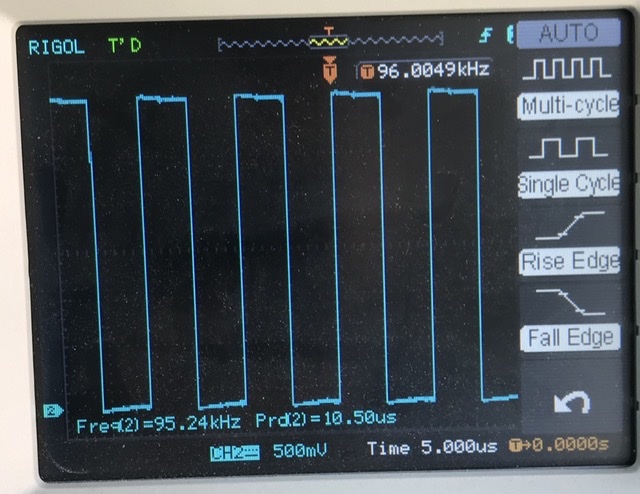
  • PSSYNC1 (2nd picture 3.3VPeak, switch-off: 0V)
  • GND
  • +3.3V KEEP ALIVE (3.3VDC always)

If I just pitch-off the 8-pin connector - the voltage supplied to the main-board remains the same, but the system cannot be switched-on anymore. Just wondering what I could do that the system runs without the 8-pin-cable connected to the original power-supply-pcb.

The “switch” is a button connected to the main-board.

Any hint is very much appreciated!

1st picture: main-board (top); power supply (bottom)

2nd picture: 3.3VPeak signal of PSSYNC1 when system is running

3rd picture: 3.3VPeak signal of TEMP3

\$\endgroup\$
5
  • \$\begingroup\$ Am I just missing the question here? Are you asking why it doesn't turn on if the 8 pin connector isn't connected? \$\endgroup\$
    – Ron Beyer
    Commented May 27, 2020 at 15:48
  • \$\begingroup\$ @RonBeyer - sorry YES you’re completely right! (I added this one now) I am wondering what can be done that it is working without the 8-pin-cable being connected to the original power-supply-pcb \$\endgroup\$
    – Martin Z
    Commented May 27, 2020 at 15:50
  • \$\begingroup\$ I'd measure what is on "n power off" and then make sure that it isn't pulled down to ground on the board. If it is, you'll have to tie it high to make it come on. \$\endgroup\$
    – Ron Beyer
    Commented May 27, 2020 at 15:53
  • \$\begingroup\$ @RonBeyer - As I am not able to switch the system “on” while the 8-pin-cable is disconnected here are my measured values when system is connected to the socket but “switched-off”: on the original power-supply-pcb the Pin “nPower_OFF” is at 5.8VDC and 1.6VDC respectively on the mainboard \$\endgroup\$
    – Martin Z
    Commented May 27, 2020 at 15:56
  • \$\begingroup\$ @RonBeyer Thank you very much for your Input it helped me a lot figuring out the solution! Will post ASAP \$\endgroup\$
    – Martin Z
    Commented Jun 19, 2020 at 12:25

1 Answer 1

0
\$\begingroup\$

So after a long break I returned to the project and I was able to solve this. It turned out that the Pin “+3.3V” of the “Mainboard” had been tied to HIGH (3.3V) by the Power-Supply PCB. Thanks to @RonBeyer I got the idea of testing it this way.

MY SOLUTION: As mentioned in the question above I replaced the Power-Supply-PCB by the following:

To get the 45.5VDC from around 12VDC (car battery):

  • 1200W 20A DC Converter Boost Constant Step-Up Power Module 10-60V to 12-83V (just a no-name product being sold everywhere e.g.: eBay)

As the loudspeakers main-board also requires 12VDC and I was not sure on how it would react to a fully charged 12V battery (max 14.2V) I added a step-down buck-converter like this:

For the 5VDC supply I also used the buck-converter from above.

In order to tie the mentioned 3.3V Pin to HIGH I used a very small/cheap step-up/down module from Amazon (for the input I used 5VDC from the bucket converter above)

Additionally I added a relay for switching on/off the power-supply.

I hope this helps someone.

The complete project with replaced power supply

\$\endgroup\$

Not the answer you're looking for? Browse other questions tagged or ask your own question.