3
\$\begingroup\$

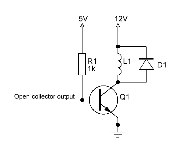
Assuming the value of R1 is the correct value for the base resistor for the given motor L1, is it okay to omit the additional base resistor, used in push-pull applications, for an open-collector output?

To my understanding, when the open-collector output goes low, the low impedance path will not affect the transistor negatively, as there is no/minimal potential difference between the open-collector output directly connected to the base and ground, therefore turning-off the transistor.

Schematic

This is my proposed solution using an N-channel MOSFET, based on the helpful answer of @Spehro Pefhany: N-channel MOSFET solution
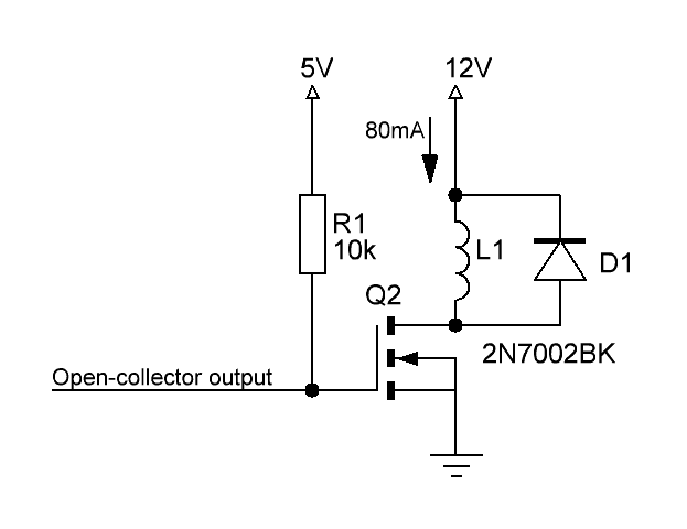
I'd much appreciate feedback on this proposal. Will it work with a good margin both at 5V and 12V motor (L1) voltage and over a temperature range of 10°C to about 85°C?

These are the links to the datasheets:

\$\endgroup\$

2 Answers 2

4
\$\begingroup\$

Maybe, but you need to ensure that the Vol from the open-drain output guaranteed to be sufficiently low to ensure that the transistor is fully off under worst-case conditions with the value of R1 that you need to properly drive the base (typically something like the relay coil current divided by 10 or 20).

A guarantee of 300mV is usually sufficient.

Otherwise, you can use a pullup resistor and a voltage divider to the base, or maybe use a MOSFET, which could allow a higher value of R1.

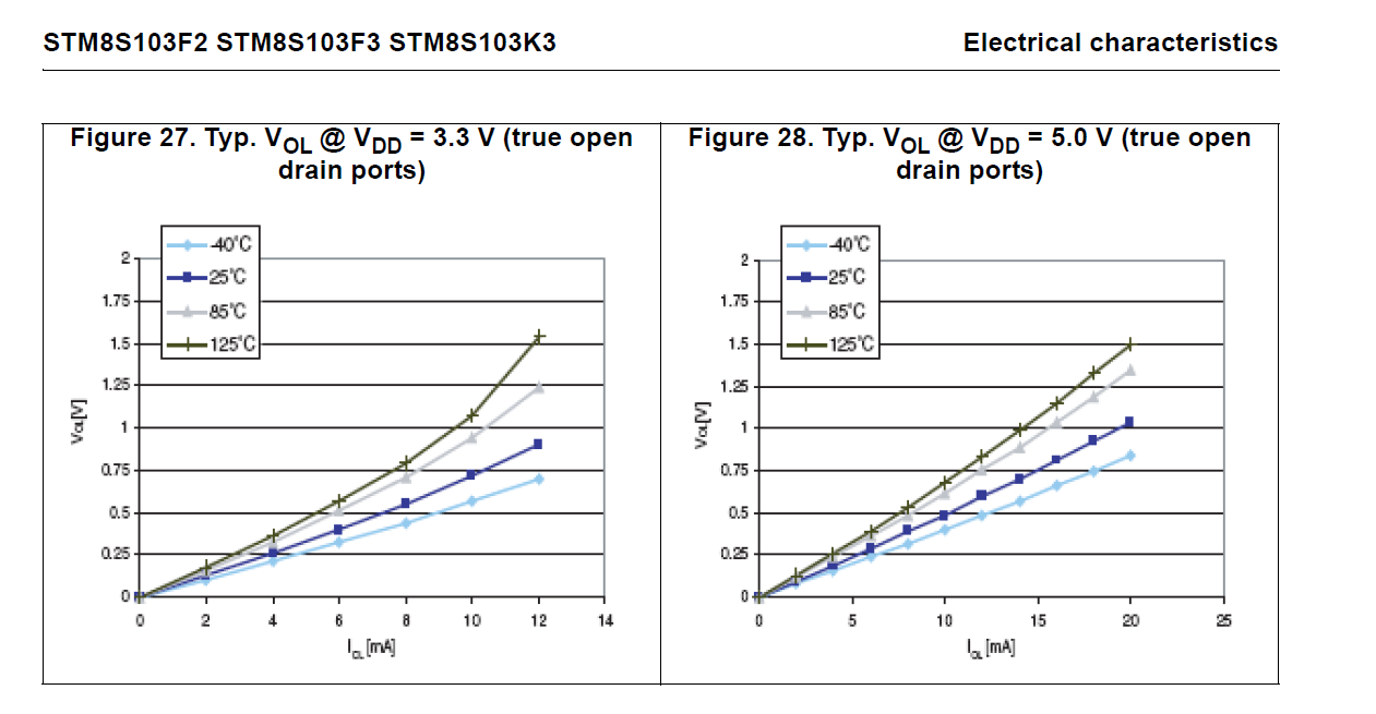
For example, here are the typical characteristics of the open-drain outputs on the STM8S103F3 microcontroller datasheet (that I happen to have open at the moment):

enter image description here

None of the guaranteed numbers are directly useful, but combining the two it looks like 3mA would be safe with a 5V supply, so a 30-60mA relay could be driven as suggested.

\$\endgroup\$
3
  • \$\begingroup\$ Comments are not for extended discussion; this conversation has been moved to chat. \$\endgroup\$
    – Voltage Spike
    Commented Jan 23, 2021 at 18:31
  • \$\begingroup\$ How unfortunate for future readers. The comments contained the whole solution. \$\endgroup\$ Commented Jan 23, 2021 at 19:16
  • 1
    \$\begingroup\$ Summary: Use an SOT-23 logic-level MOSFET with Vt > 650mV and a 10K pullup. \$\endgroup\$ Commented Jan 23, 2021 at 19:18
2
\$\begingroup\$

is it okay to omit the (extra) base resistor for an open-collector output

YES

But don't assume R1 is optimal.

To get rated current in the coil, The datasheet will show its DCR use 10x that value for pullup scaled by the voltage ratio 4.3/12 thus if DCR = 80 Ohms, R1= 800 *4.3/12= 287 Ohms or nearest preference. 330 to 280.

Very high hFE transistors will use 20x factor.

\$\endgroup\$
2
  • 1
    \$\begingroup\$ It should work fine, the MOSFET has a VGS(th) of 1.1V therefore you must insure the gate goes well below that; 0.7 volts is fine. Also note a MOSFET is a voltage controlled device unlike a BJT which is current controlled. The concern with the MOSFET is that you turn it on reasonably fast the gate does not control the gain in an enhancement MOSFET. \$\endgroup\$
    – Gil
    Commented Jan 23, 2021 at 16:37
  • 1
    \$\begingroup\$ for a 150 Ohm Fan almost any BJT or FET switch will work and startup speed is limited by load capacitance inside fan \$\endgroup\$
    – D.A.S.
    Commented Jan 23, 2021 at 16:44

Your Answer

By clicking “Post Your Answer”, you agree to our terms of service and acknowledge you have read our privacy policy.

Not the answer you're looking for? Browse other questions tagged or ask your own question.