Because it just is single phase
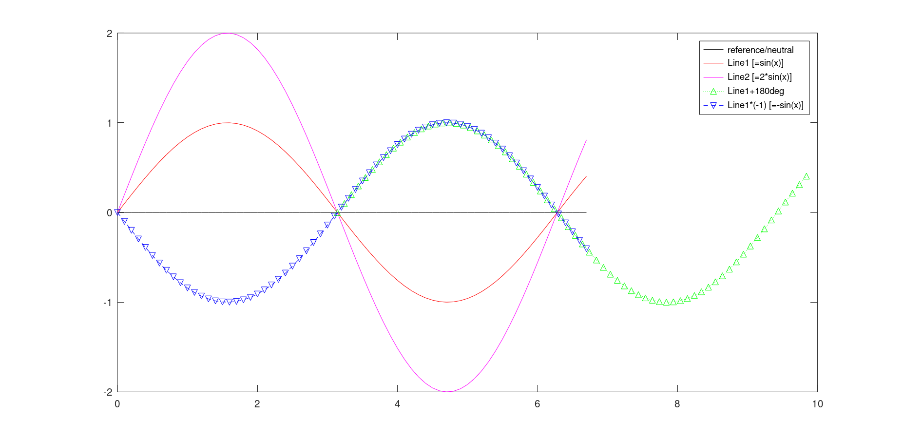
 Octave code:
x = 0:0.1:(2*pi+0.5);
plot (x, (x-x), "-k;reference/neutral;", x, sin(x), "-r;Line1 [=sin(x)];", x, 2*sin(x), "-m;Line2 [=2*sin(x)];", x+pi, sin(x), ":^g;Line1+180deg;", x, -sin(x), "--vb;Line1*(-1) [=-sin(x)];")
#1 - ground at one outer tap
- Black reference/neutral is the grounded outer tap (=GND henceforth in this post).
- Red Line1 is the middle tap with
120Vrms to GND.
- and Magenta Line2 the other outer one with
240Vrms to GND.
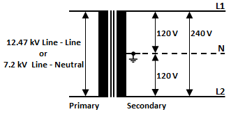
Voltage between Line1 and Line2 is 120Vrms too. -> 120V+120V=240V -> these two "120Vs" must be in phase and not 180° out of phase or you wouldn't get 240V.
As shown/stated by @vu2nan the pole transformer has just one primary/input winding and only one core and one output winding (with a center tap). Even if different phases were to arrive at the primary winding (which is electrically impossible) the winding itself would only swing with the sum of those phases (replace phases with frequencies in this sentence and it makes sense...).
Thus everything on the secondary winding must be in one phase too (there may be an exception if the transformer isn't magnetically/mechanically balanced mirror-able).
#2 - GND at center tap eg. "split phase"
- Black is the GNDed center tap.
- Red Line1 is the 1st outer tap L1 with
120Vrms to GND.
And you have two options for the 2nd outer tap L2:
- it has exactly the same voltage profile as L1 / Red Line1 when you measure from GND to L1 and from L2 to GND. (use a scope where inputs 1+2 have completely isolated inputs including there grounds or two separated scopes with synced triggers(?). Basically if you measure exactly as in #1 but with a shifted GND.)
- or it's Blue/Line1
*(-1), the inverse of L1 when you measure from GND to L1 and from GND to L2 (eg. flipped #1).
This doesn't change anything with the phase. It's still just one phase and not out of phase by 180° (or any other degree).
To mathematically get 240Vrms here between L1 and L2 you have two options again (with 1 on the y-axis being equivalent to sqrt(2) * 120V):
sin(x) + sin(x) = 2*sin(x)sin(x) - sin(x+pi) = sin(x) - -sin(x) = 2*sin(x)
but sin(x) + sin(x+pi) = sin(x) - sin(x) = 0 (one 180° out of phase to the other)
Now if you want to add two times 120V together they need to be in phase. If their phases are pi-shifted you need to subtract(!) both potentials from each other to get 240V.
Mathematically the result is the same but one is is a bit more counter intuitive (from this perspective).
Why the term "phase" is out of place (here in my opinion)
Short: If you first learn this split phase out of phase you need to re-learn it when you want to work in electrical power distribution and so on (in the US you have multi-phase AC there too?).
Much longer....
Phase is usually only used with n-phase systems (with n>1) in relation to the generators.
Imagine a simplified/idealized generator with just three stator coils in star configuration 120° apart from each other and one bar-magnet as the rotor.
Now if you start to turn this generator with 60rpm = 1Hz there is a 'real' phase difference between the three outputs when you compare the sinus waves between any two random but different pairs of measuring points (L1/2/3). The V-peaks on each pair follow each other 1/3 *s apart (or 120°).
Example: L1~L2 has it's V-peak 1/3s before L2~L3 but 1/3s after L1~L3. I used "~" instead of "-" here because the polarity is irrelevant for the phase. If you measure one pair in the opposite direction to the other one it's up to you to use the inverse or you'll falsely think the rotating field suddenly switched direction which can quickly lead to catastrophes (as if a big gas turbine would suddenly switch directions).
In other words: You need to decide on one rotation direction and measure along the Ls that way top get a correct result. If you switch directions in the same set of measurements the result cant be trusted.
When you you have only one phase you have no rotating field at all and cant have any 'true' out of phase "phases"...
2nd example: If you connect a new power plant to the grid and the generator is not exactly in phase with the grid it will either be sped up or slowed down by the grid to get it in phase (the grid will do the opposite but it's rotational momentum is far greater so this effect is negligible). If it's too far out of phase (eg. by 180°) it will probably destroy itself, some transformers, the turbine and more...
This out of phase doesn't really relate to the split phase system's out of phase.
Another example: modern eg. DUSPOL voltage testers and equivalent can measure the rotation direction of/between just two phases of a three phase system by - I'm not actually sure how - maybe measuring the time between V-peaks (or with a capacitively connected third pole through the handlers hands - need to test that)?
The problem with that is: Under ideal conditions you get a perfect sinus wave between two phases regardless of variations in phase difference or if it's L1~L2, L2~L3 or L3~L1. Reason is that the sum of any two sine waves with the same frequency (eg. 60Hz) and any phase shift of f<>pi is another sine wave, just with a different amplitude. (If f=pi=180° the sum is 0)
But If one measures between GND and any of the three phases the voltage tester randomly flips between right and left rotation.
It would be the same in a single phase center taped system - no or randomly flipping rotation direction but between any pair of measurement points (not just between GND and L* but between Lx and Ly too).
The phase offset I know of is in direct relation to the mechanical construction of a multi-phase generator (degree between sets of coils and if two sets are 180° apart they are connected so they are in the same set...).
Why Wikipedia says "Two 120 V AC lines are supplied to the premises which are out of phase by 180 degrees with each other (when both measured with respect to the neutral)" is beyond me.
As if split phase alone wouldn't be the source of enough confusion, let's throw in an out of phase.
Much better would be (imho): Two 120V AC to ground lines are supplied to the premises with 240V between the two
And maybe add (which means with respect to the grounded center tap both AC lines are inverted relative to each other)
but leave phase out if it...
RE your kinda vague questions
The common North American residential power is not a 2-phase system by any reasonably accurate technical definition.
Why the confusing term split phase is used instead of eg. center tapped single phase - which would be exact, accurate and technically correct - I don't know.
The reason is purely technical but kinda depends on how you define phase in this regard. As the mathematical/physical time offset of different sine waves of the same frequency with and/or ;-) without regards to polarity.
For time offset take look at the green wave from the graph.
Calling them out of phase is very misleading imho. Maybe phase shifted? Don't like that much more so maybe phase inverted?!


