-3
\$\begingroup\$

Excess solar power needs to be dumped into a lithium based battery (load). The battery's charging voltage is 54 V. The battery has protection for over and under voltage and upper current limt and that is not of concern.

This question asks for a circuit to make an adjustable current limiter based on a reference input voltage. The current limiting (i_l) changes as the voltage changes:

i_l = f(v)

Where f(.) is the limiting function implemented by the circuit and v is the controlling voltage and is in the range of 0.3 to 3 V. At v = 3 V, i_l is the maximum allowable current and is 35 A. At v = 0.3 V, i_l >= 0 A and thus as v is reduced, the current limit of the circuit is reduced.

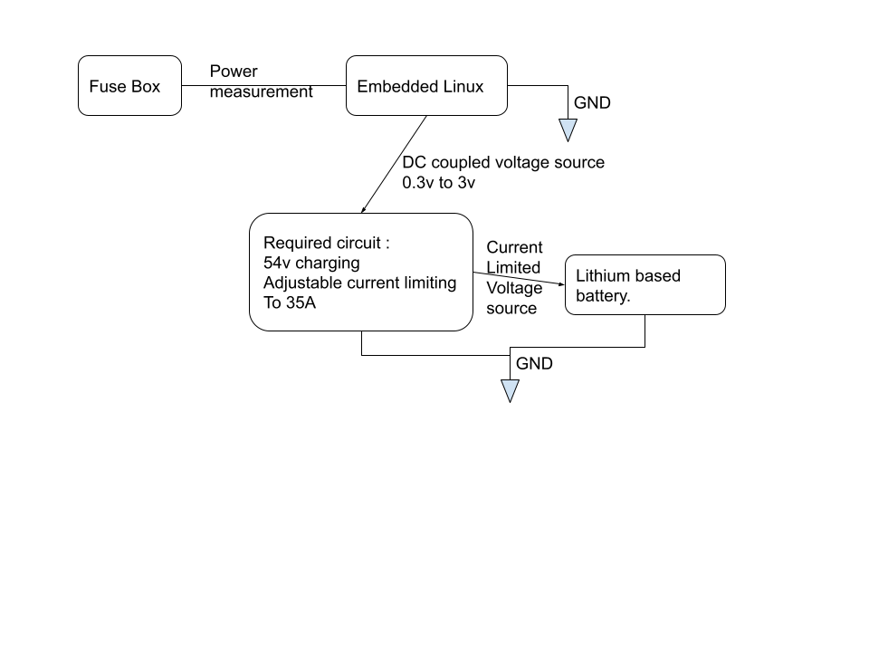
Here is a block diagram : enter image description here

I am aware that off the shelf programmable voltage sources are available, which allow adjustable current limiting, however I would like to implement this circuit myself.

This question is how to implement a controllable current limiter based on a reference voltage.

\$\endgroup\$
15
  • 2
    \$\begingroup\$ Wasn't this not only here and closed but also perhaps earlier, as well? \$\endgroup\$
    – jonk
    Commented Sep 15, 2022 at 22:08
  • \$\begingroup\$ It's not completely clear what the actual V I control and limit requirements are. Must it be constant voltage with a programmable current limit (at which point of course the voltage drops)? This sounds like a remote controlled 2 kW mains power supply, could you just buy one like this? \$\endgroup\$
    – tomnexus
    Commented Sep 15, 2022 at 22:13
  • 5
    \$\begingroup\$ @Matt When your question gets closed, edit the question to address the close reason. Deleting a question and asking it again is not allowed on this site. A closed question can be reopened if its problems are addressed. \$\endgroup\$
    – Hearth
    Commented Sep 16, 2022 at 0:42
  • 5
    \$\begingroup\$ Question is not clear at all to me. I read it several times. This is just some feedback to the OP. It is possible that this lack of clarity is causing some people (not me) to vote to close. I think the question could be made MUCH more clear by adding a block diagram of all the system components. \$\endgroup\$
    – user57037
    Commented Sep 16, 2022 at 4:55
  • 1
    \$\begingroup\$ Drive-by comment (I didn't vote on the closure or the question) - I'm inclined to agree with the closure, because the question is still not actually clear. To get an answer more effectively, help us help you by making your actual spec clear and unambigous, without needing to guess at unspecified assumptions and design decisions you've already made. \$\endgroup\$
    – nanofarad
    Commented Sep 17, 2022 at 3:14

1 Answer 1

1
\$\begingroup\$

There are several ways to do this: One would be to find a DC DC controller with a current limiting pin that is settable by a resistor, then use a digipot to set the current limit.

Another way would be to find a DC DC controller that has both voltage and current control. Usually these have voltage inputs that could be controlled with a DAC.

Vicor has some isolated supplies that have trim that can be used for current limiting

Here are some other ideas:
Digital control CC/CV boost DCDC chip/module?

Precision circuit that is CC and CV circuit or power supply

\$\endgroup\$

Not the answer you're looking for? Browse other questions tagged or ask your own question.