6
\$\begingroup\$

Are there any hobbyist-affordable non-isolated DCDC boost chips or modules which could be controlled digitally via microcontroller with internal digital CC/CV support? Surely, it is possible to use regular boost IC, stick there bunch of opamps, ADC, DACs... It's a mess and alot of work.

Maybe there are some DCDC modules with LCD displays (like these) which are easily hackable to get full digital control over them? Or I have to use regular boost modules and hack in digital potentiometer/manually sense current?

For this application I need to step up 48V to ~90V with 0-700mA (LED strip) current with 10 independent channels.

Update: ideally this is some sort of IC which I can operate like lab power supply: send via I2C commands like "V=37.32 I=0.371 ON" - and it works in CC/CV mode automatically like a lab power supply. But I2C controlled LED driver which can only do CC would work too, if I can set and sense current.

\$\endgroup\$
3
  • \$\begingroup\$ ADP1046A comes to mind. \$\endgroup\$
    – winny
    Commented Sep 20, 2017 at 7:42
  • \$\begingroup\$ @winny added a not that this would need to be non-isolated... ADP1046 is too complicated as it's isolated. \$\endgroup\$ Commented Sep 20, 2017 at 20:24
  • 1
    \$\begingroup\$ No no, you can use it with any topology you want, including non isolated. There are others in the same family too. \$\endgroup\$
    – winny
    Commented Sep 20, 2017 at 20:42

5 Answers 5

2
+150
\$\begingroup\$

There are a lot of requirements in this question:

1) Price estimate <30$ per module
2) Support CC/CV
3) Digital Control
4) 48V input
5) 90V output
6) 700mA current
7) Module (not IC)

You are probably not going to find something that matches all those requirements, ideally there would be. A good system designer will come up with a list of requirements, but then check to make sure the list of requirements will be possible. If its not possible, then the list needs to be revised with a priority attached to each requirement. I was only able to find designs that met 5 of the requirements, but not all 7. This suggests that the requirement list needs to be revised.

If I drop requirement number 1) and 2) this is found: 36IBX15-50-0G There are less than 5 modules on digikey that fit all of the requirements and none of them are controllable and they are all expensive, this suggests that if you want a module you'll immediate be out of budget if you order from north American suppliers.

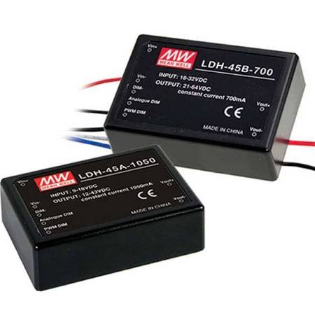
This Mean Well LDH-45 series can be had for ~10$ and has PWM dimmable control and analog control, however it does not satisfy requirement 4) because it has a 32V max input, in this case, it would probably be cheaper to switch to a module like this and get a new power supply. It also doesn't really do CC/CV, but does have PWM control which makes it digitally controllable so requirment 2) is also nixed.
enter image description here

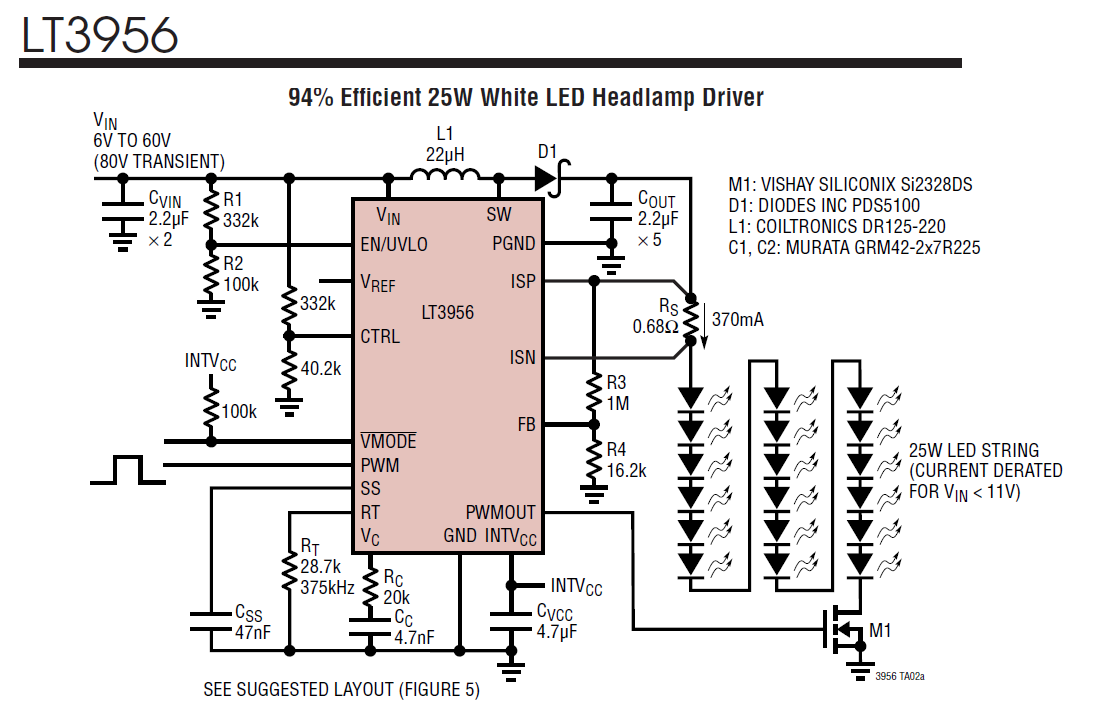
If I drop requirement 7) and 5) I get the LT3956. With engineering usually time and cost are traded off. There are other IC's that would If you have time, then use an option like this and do a PCB design. PCB web takes most of the confusion of PCB design. (they already have most of digikey's stock in the PCB web library which means you don't have to keep track of parts or draw footprints 98% of the time, it generates a bom and you can automatically order the PCB) If cost is an issue, then this would be the way to go. However there are no IC's searchable on digikey that will boost to more than 80V. Yes it's more complex, but if you have some smarts usually implementing a design from a good datasheet schematic will be fairly easy. If you go this route, make one or two (you can even have them assembled) to make sure it works and then make 10.
enter image description here

There are too many requirements for this project, you could change a few of them. Pairing down the 48V Input requirement would give you more flexibility to choose modules that might have a digital option. If you split your 90V requirement and split your LED string in half, then you could also open more modules up as good candidates. If your going for price, then roll your own PCB, this also give you more flexibility.

\$\endgroup\$
1
  • \$\begingroup\$ Your comment was especially useful. I decided to ditch 48V supply and go for 24V and LDH-45 modules. Will yield 80% of result with 10% of effort. \$\endgroup\$ Commented Oct 2, 2017 at 4:01
5
\$\begingroup\$

Yes. What you want is called a microcontroller. Seriously.

There are whole families of micros that are targeted to switching power supply control. Take a look at "motor control and power conversion" parts of the Microchip dsPIC series, for example. These micros have a time base, fast A/D converters, and PWM output generators all built in. You want to step up 48 V to 90 V at 700 mA. That really isn't all that hard.

For example, you could run the A/D and PWM synchronized together at 100 kHz. That means every 10 µs you get a new A/D reading of the output voltage, then decide what length pulse to produce for the next PWM period.

A simple pulse on demand scheme might even be good enough. You can set that up with no firmware overhead at all once it's up and running. I've done exactly that several times in real commercial products to create various auxiliary supply voltages. You can get micros that have internal analog comparators, and PWM generators with fault inputs. The comparator output can be configured to disable the PWM pulse stream when a external voltage gets too high. This automatically regulates the output voltage.

Since you want to drive LEDs, you can use this scheme with current feedback instead of voltage feedback. When the voltage across a low side current sense resistor gets to the threshold level, the comparator trips and shuts down the PWM generator. There are micros with internal voltage references which can be internally tied to one of the comparator inputs. A few 100 mV for a current sense resistor isn't much compared to 90 V.

If the pulse on demand scheme is good enough, then even the tiny and cheap PIC 10F204 is all you need. It has a analog comparator and 600 mV reference built in. When the sense resistor output is below the 600 mV threshold, you do a pulse, then go back and look at the comparator output again.

This is exactly how my KnurdLight works. It controls the current thru a LED string. In this case, the LED string needs about 13 V at 20 mA. However, the code in the PIC would be the same.

\$\endgroup\$
3
\$\begingroup\$

What I would suggest is using a current controlled boost controller such as the LM5022 for each channel.

You would need to measure the output current with your microcontroller ADC, which can be done easily using a sense resistor plus an op-amp. You could measure the output voltage with a simple resistive divider plus capacitor.

To control the LED current, the microcontroller should generate a reference signal for the boost controller IC via a DAC or a timer/LPF. You would need to implement a simple control loop in the uC that adjusts the reference current signal based on the measured current/voltage. A simple integral controller would be fine.

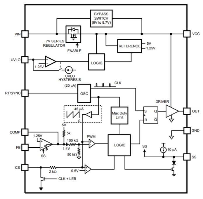
To 'hack' the current controller IC, you should route the reference voltage of the uC directly to the COMP pin of the IC. For example, you can see in the block diagram below, the COMP pin is directly connected to the output of the error amplifier for the LM5022. For this particular chip, the output of the error amplifier is open collector, which means that the onboard error amplifier can be disabled by connecting the FB pin to ground. The FB pin won't interfere with the output of the microcontroller.

Obviously you would need some kind of analog mux circuit if your microcontroller doesn't have enough ADC inputs or DAC outputs.

enter image description here

\$\endgroup\$
2
\$\begingroup\$

You could use LT3756 as the driver, it takes PWM input so an I2C PWM chip like PCA9685 gives you 12 channels PWM... You can also control the driver in analog mode if you want.

\$\endgroup\$
5
  • \$\begingroup\$ LT3756 looks very close, if only It had digital input instead of PWM, so that I can send commands like "set current XXXmA or something like that" \$\endgroup\$ Commented Sep 22, 2017 at 18:37
  • \$\begingroup\$ If you want to drive LEDs, then why the CV setting? A simple overvoltage protection is sufficient in case the LED is disconnected... \$\endgroup\$
    – bobflux
    Commented Sep 22, 2017 at 18:55
  • 1
    \$\begingroup\$ @BarsMonster Most LED drivers for this level of power are PWM-driven, anyway. But you can use a PWM output from your MCU: sending a "set PWM duty cycle to xx%" command to a PWM integrated in a MCU isn't more difficult than sending a "set current to xxxmA" command to some external I2C chip. \$\endgroup\$
    – dim
    Commented Sep 23, 2017 at 21:16
  • \$\begingroup\$ @dim I see your point, it will work, but it just looks so old-fashioned and rudimentary. This dummy intermediate PWM seems so rudimentary... I am not talking about using I2C->PWM chip - this is also rudimentary. Ideally DCDC controller should be controlled by I2C directly, with digital values for target current and voltage... \$\endgroup\$ Commented Sep 25, 2017 at 12:26
  • \$\begingroup\$ Sure, motherboard CPU VRM works like that, but it looks like no manufacturer has bothered making a I2C-controlled LED driver with the voltage you need... Probably because there wouldn't be enough buyers for this chip ;) \$\endgroup\$
    – bobflux
    Commented Sep 25, 2017 at 12:29
1
\$\begingroup\$

There's a ton of I2C digitally programmable battery chargers used on laptop motherboards that will let you control voltage and current. For example, the ISL9237.

You could also get your hands on Microchip's Hybrid PWM Controllers and do a touch of PIC programming. They have all the required analog + drive circuitry internal to the part. That way would could bypass the I2C interface all together and use the PIC to do other things while it's regulating. For instance, check out the MCP19123.

\$\endgroup\$

Your Answer

By clicking “Post Your Answer”, you agree to our terms of service and acknowledge you have read our privacy policy.

Not the answer you're looking for? Browse other questions tagged or ask your own question.