1
\$\begingroup\$

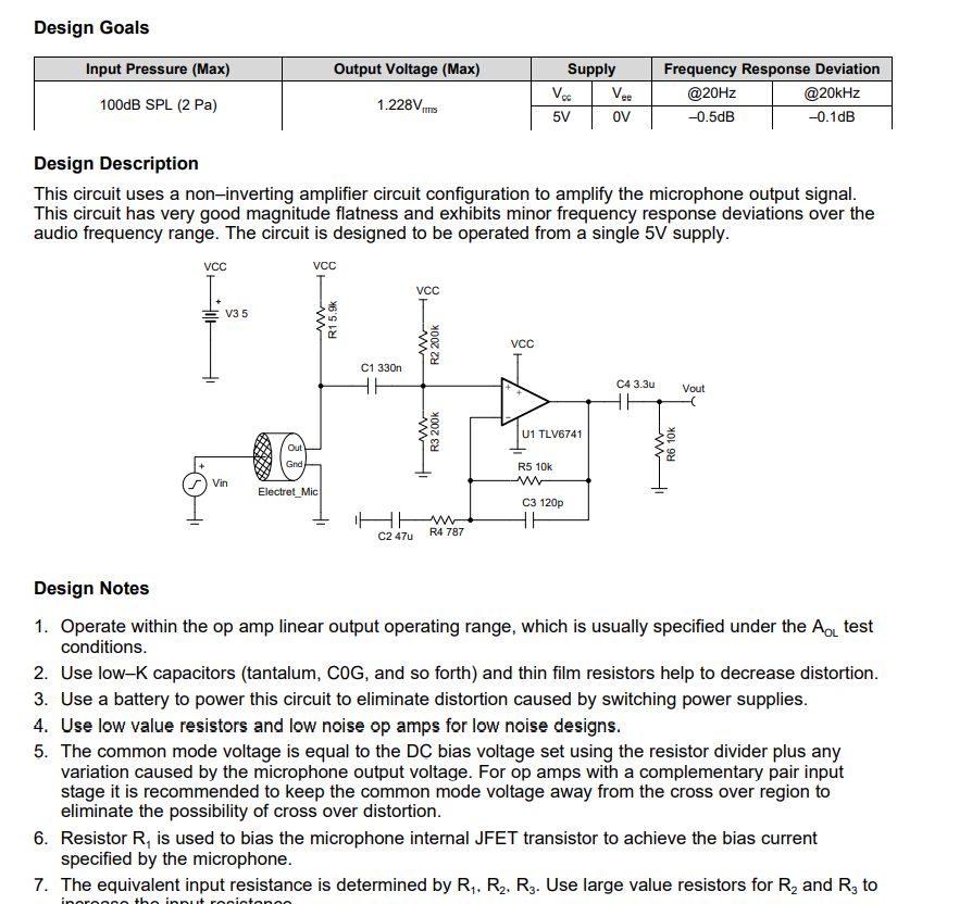
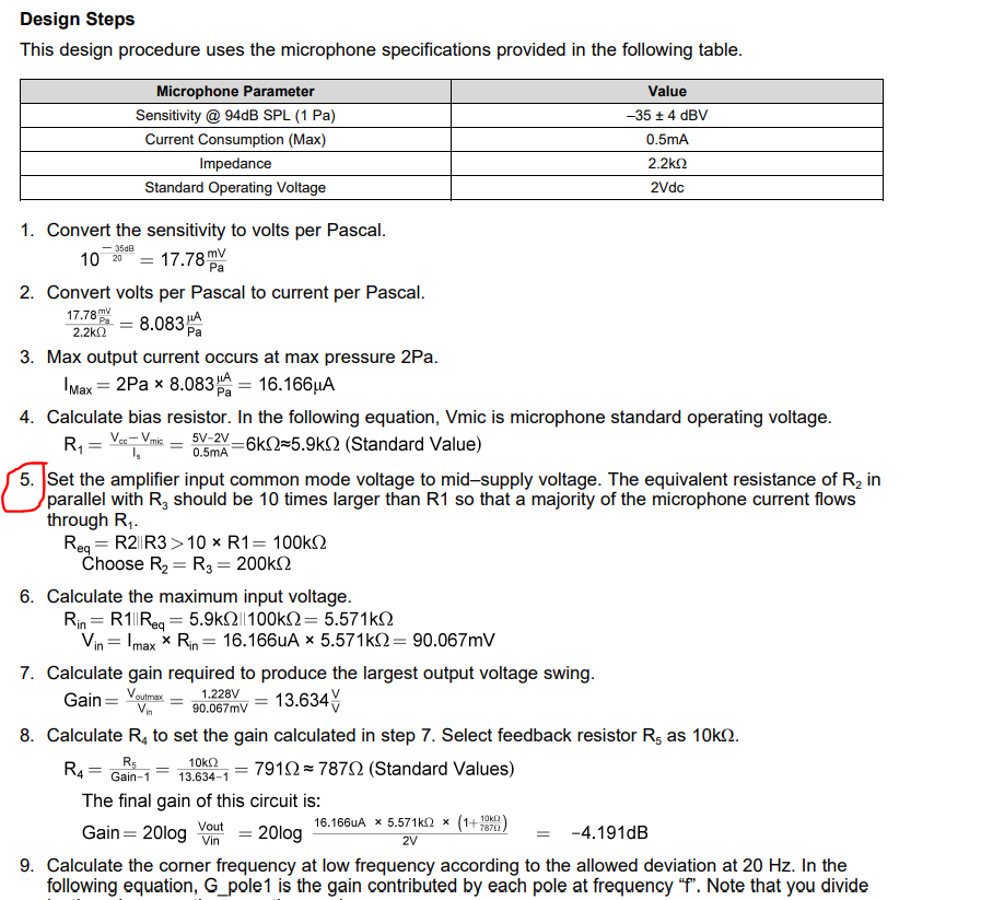
I don't understand the need to set the amplifier input common mode voltage to mid–supply voltage in the circuit below. What does it do and why is it needed?

In equation (7) the authors address VoutMax as 1.228V and not 1.228Vrms. What's the difference?

Are those RC circuits and other capacitors really needed? What happens if I ignore them?

enter image description here

enter image description here

The author of these images is Texas Instruments: Non-inverting microphone pre-amplifier circuit

Edit:

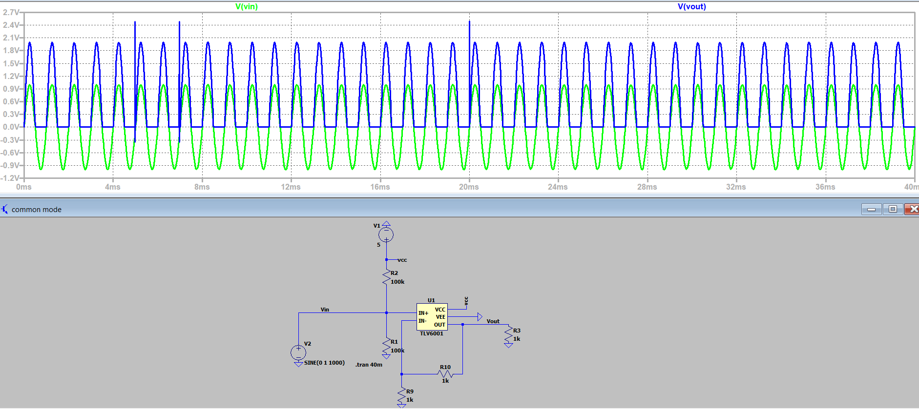
So i tried doing part of that circuit in LTSpice with an opamp that is also rail to rail at the output:

enter image description here

The output signal is not centered at the output, why is that?

\$\endgroup\$
6
  • 2
    \$\begingroup\$ The TLV6741 does have a rail-to-rail output but it most certainly doesn't have a rail-to-rail CM input. In fact, at \$V_{_\text{CC}}=+3.5\:\text{V}\$ as shown, the input CM range only reaches to \$+2\:\text{V}\$ and down close to ground. Setting it to center on \$+1.75\:\text{V}\$ isn't my idea of a better quiescent input location for that particular opamp. There's only \$250\:\text{mV}\$ of top end headroom. Sure, that's enough given their calculations for the input. But I'm not comfortable with it sans more detail and it certainly is not a requirement (nor necessarily good design.) \$\endgroup\$
    – jonk
    Commented Nov 26, 2022 at 5:30
  • \$\begingroup\$ What exactly is rail to rail cm input? \$\endgroup\$
    – Scipio
    Commented Nov 26, 2022 at 14:16
  • 1
    \$\begingroup\$ Take a look at this on the datasheet. That's the problem I see. Do you see the \$-1.2\:\text{V}\$ part, there? \$\endgroup\$
    – jonk
    Commented Nov 26, 2022 at 19:28
  • 1
    \$\begingroup\$ I'm not the one who made it up, so I can't pretend to be able to read old, dead minds. But I think it's called 'common mode' because the two inputs may have differences between them (the AC part) and shared parts, too (the DC offset part.) So if the inputs were, say 2.1 V and 2.3 V, then the differential part is plus or minus 0.1 V (or 0.2 V total difference) and the DC part is 2.2 V (the common part.) Just another way of saying the same thing, really. Opamps inputs work only 'so close' to their rails. Those that can do it 'very close' are 'rail-to-tail input'. This isn't one of those. \$\endgroup\$
    – jonk
    Commented Nov 26, 2022 at 19:40
  • 1
    \$\begingroup\$ There is usually a current mirror in the input stage. It can either be on the high side, which means the inputs cannot 'squish too close' to the upper rail or else it is on the low side, which means the inputs cannot squish too close to the lower rail. Some have very special input designs that allow their inputs to work very close to the rails. These will often pair up two mirrored diff-amps but I don't have a comprehensive view, either, so I can't say all of them do. \$\endgroup\$
    – jonk
    Commented Nov 26, 2022 at 19:45

3 Answers 3

3
\$\begingroup\$

What's the need to set the amplifier input common mode voltage to mid–supply voltage in this non-inverting microphone pre-amplifier circuit?

By setting the quiescent voltage of the non-inverting input of the op-amp to the midpoint between the power supply rails, the amplifier has is able to output the largest signal without clipping/distortion/saturation.

If the quiescent voltage of the non-inverting input were closer to one power supply rail than the other, then there would be some amplitude of input signal that would cause the output (prior to the output capacitor) to reach its maximal value (limited by the supply rail).

In equation (7) the authors address voutmax as 1.228V and not 1.228Vrms, what's the difference?

When a voltage is specified for an AC signal, and it does not explicitly state peak-to-peak, or peak, then usually rms is meant. However, this is not an absolute. There are exceptions.

Also, are those RC circuits and other capacitors really needed? What happens if i ignore them?

Yes, they are needed, and if you ignore them, the circuit will not work correctly. The input and output capacitors are needed so that the input and output can be free of DC, while the op-amp works with a DC offset set at the midpoint between the power supply rails. The resistors between the input capacitor and the op-amp input are needed to set the quiescent voltage for the non-inverting input. The resistors and capacitors that connect to the inverting input are a feedback network. It is necessary to properly set the gain for the amplifier, which is primarily necessary to make the amplifier linear (i.e. free from amplitude distortion).

\$\endgroup\$
7
  • \$\begingroup\$ Ok, so if the mic outputs a negative signal and it passes through that opamp the negative part of the signal will be clipped, that's why we use those 2 resistors forming a voltage divider. So the output signal should be come out centered in 2.5V? Also, i understand why the first capacitor in the inpu part is there for. But that last RC circuit in the ouput what is it for? The gain doesnt depend on anybof the output capacitors \$\endgroup\$
    – Scipio
    Commented Nov 26, 2022 at 2:40
  • \$\begingroup\$ @G0tBlackOps Yes. (Assuming you keep the power supply at 5V). \$\endgroup\$ Commented Nov 26, 2022 at 2:41
  • \$\begingroup\$ The output of the opamp comes out centered around 2.5V (or whatever VCC/2 is). That means there's a DC component of 2.5V and a small AC voltage (the audio) superimposed on it. The AC component then passes through the final output capacitor C6, but the DC component is blocked by it. The DC level of the output side of C6 is set by whatever R6 is connected to, ground in this case. So, the final output Vout is your amplified audio, centered around ground. \$\endgroup\$
    – td127
    Commented Nov 26, 2022 at 3:01
  • \$\begingroup\$ @td127 why use capacitors C2 and C3? The gain doesnt depend on them \$\endgroup\$
    – Scipio
    Commented Nov 26, 2022 at 14:49
  • \$\begingroup\$ @G0tBlackOps the gain is frequency dependent in this case. The combination of the 2 resistors and 2 capacitors form a band-pass filter. This is useful in audio circuits because noise at frequencies above or below the audible range can adversely affect overall signal quality. Whether or not an input causes amplifier saturation depends not only on the instantaneous signal amplitude, but also on the instantaneous noise amplitude. So it is useful to attenuate at frequencies outside of the audible band. You could omit those capacitors, but at the risk of possible distortion. \$\endgroup\$ Commented Nov 26, 2022 at 15:00
2
\$\begingroup\$

How do we explain circuits?

Circuits are truly understood when, in addition to the specific circuit solution, we show the general idea behind it. This allows us to show the relationship between seemingly different circuit implementations and they will be easily understood.

Biasing

What is "biasing" in electronics?

Obviously, voltage devices require their input and output voltages to be within the limits of the supply voltage; so positive-supplied devices need positive input/output voltages and negative-supplied devices need negative voltages. When signals do not meet this requirement (e.g., AC voltages which "wiggle" around ground), figuratively speaking, they must be "moved", "shifted" inside the working area... and this is called "biasing" in electronics.

How do we bias circuits?

The remedy is obvious - we add/subtract "shifting" voltages to/from the input and output voltages: for positive-supplied devices, we add constant voltage to the (AC) input voltage and subtract constant voltage from the output (AC + DC) voltage; for negative-supplied devices, we subtract voltage from the input and add voltage to the output voltage.

Conceptual bias circuit

To realize the bias idea above, we need a voltage summer. We can make it by the help of KVL, simply connecting a constant voltage source in series. The problem is that this source cannot be connected to ground; it is floating since usually the input voltage source is grounded.

Biasing capacitors

If the input signal is AC voltage, we can use charged capacitors as floating voltage sources (historically the first biasing idea). You can figuratively think of them as "rechargeable batteries". We have to keep them continuously charged to Vbias. Let's see how.

Input circuit. First at all, we have to ensure a path for the charging current through the input voltage source; so it has to be conductive ("galvanic"). Then, we have to supply the other end of the capacitor by a "bad" biasing voltage source with relatively high resistance (voltage divider). As a result, the "coupling capacitor" will charge through the input voltage source to Vbias.

Output circuit. The output biasing is similar but here the capacitor charges through the load (so it has to be "galvanic").

OP's arrangement

Now we can see all these bias elements in the specific OP's circuit.
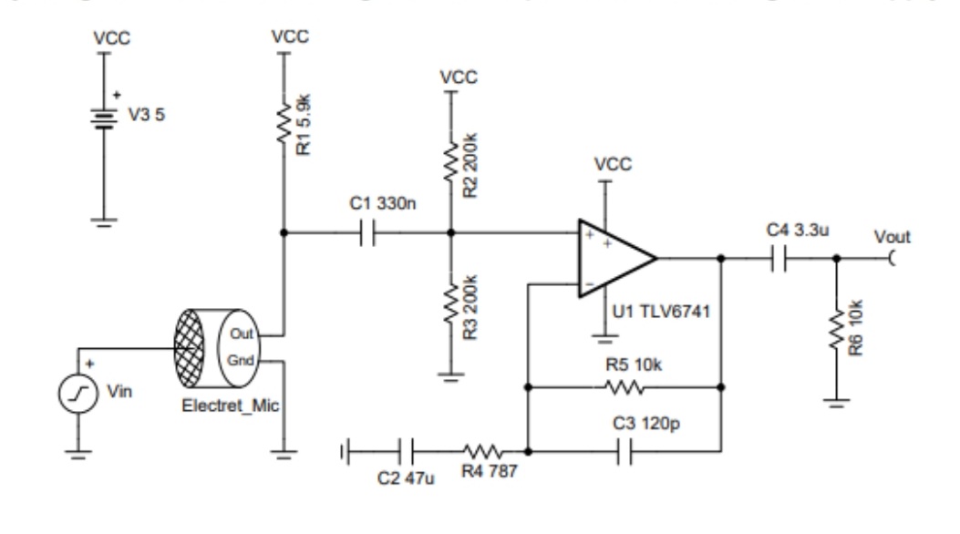
OP's circuit

A clever trick here is that the output bias voltage (the op-amp quiescent output voltage) is created by following the input bias voltage (created by the R2-R3 voltage divider).

Another trick is to connect a resistor (R6) in parallel to the load thus making it "galvanic" when needed (e.g. in the case of an open circuit).

C2 shows another capacitor application. While C1 and C4 are "moving" floating capacitors (aka "coupling capacitors") that convey the voltage variations, C2 is a "fixed", "immovable", grounded capacitor (aka "decoupling capacitor") that "freezes" the voltage variations across itself.

See also

Here are links to some of my materials related to the question:

Circuit Idea (how to understand, explain and invent circuits)

What does "biasing" mean and how is it implemented in electronic circuits?

What do coupling capacitors really do in AC amplifiers?

\$\endgroup\$
1
\$\begingroup\$

You posted a circuit that shows severe clipping at the output because an input coupling capacitor is missing. Therefore the input is not biased at half the supply voltage but instead the grounded input signal generator is at 0VDC.

C2 in the original circuit causes the opamp to have a gain of 1 at DC. With C2 replaced with a piece of wire then the DC gain is almost 14 times and the output of the opamp will be at 5VDC with no signal.

\$\endgroup\$
2
  • \$\begingroup\$ So i added an offset of 5 volts to the input signal and placed a capacitor right next to it and everything works as it should, the signal came out centered at 2.5V.... I just dont understand why it didnt work before, if i did superposition in node Vin i should get 2.5V + the sine wave? Also, how does C2 affect the gain? in equation (7) there's no C2 \$\endgroup\$
    – Scipio
    Commented Nov 26, 2022 at 20:32
  • \$\begingroup\$ C2 is a dead short at audio frequencies therefore the audio gain is 10k/787 ohms (plus 1)= 13.7 times. \$\endgroup\$
    – Audioguru
    Commented Nov 27, 2022 at 21:27

Your Answer

By clicking “Post Your Answer”, you agree to our terms of service and acknowledge you have read our privacy policy.

Not the answer you're looking for? Browse other questions tagged or ask your own question.