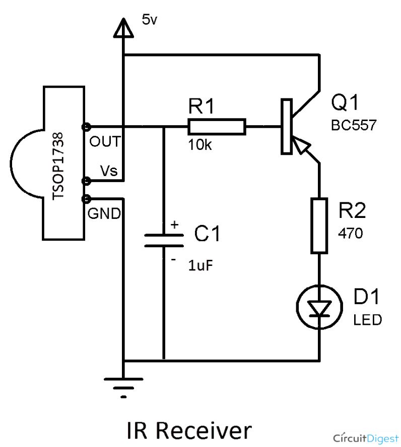
I am trying to understand how the PNP transistor configuration in this circuit works:
It comes from this article: How to build a Simple IR Transmitter and Receiver Circuit using 555 Timer?
I believe all the articles I have read about using PNP as switch would have the emitter connected to the positive supply with the load between collector and ground. However, as given it seems to work, but I don't think I understand why. (Note I am using TSOP4838.)
I would ultimately like to use the PNP transistor to replace the switch in this circuit:
Which comes from this article:
Bistable Multivibrator Using 555 Timer
The goal is to receive a pulse of IR and switch the LED between on and off in response to each pulse.


