1
\$\begingroup\$

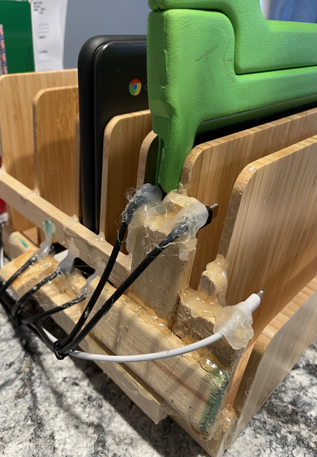
Hey all I am creating a PCB that allows me to detect when I plug in a tablet, laptop, etc. to my home made tablet organizer. It's difficult to see if it made a connection in the back since you place the tablet in the front and slide it back:

enter image description here

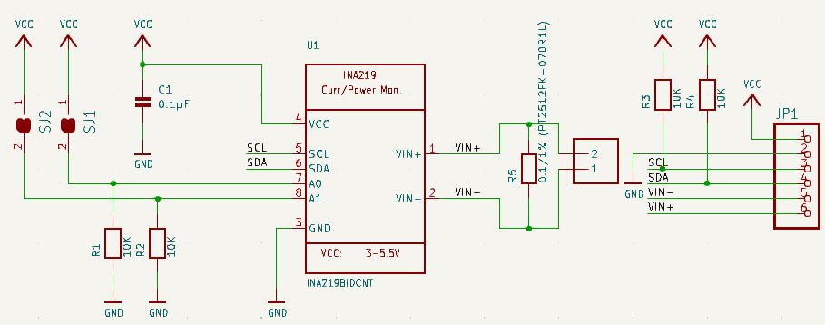
I'm using the INA219AxD and connecting the IN + and - between the 0.1/1% (PT2512FK-070R1L) resistor and having the - go to ground while the + is going to the VBUS_B line. I'm not real sure if this is the correct way to wire this in order to tell when a tablet is connected or not so that's why I need someone more knowledgeable to help me out.

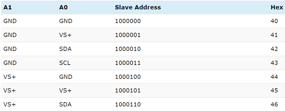
The A0 and A1 will have different resistors so that the I2c knows which one is calling out. But not sure what is needed for the 42, 43 and 45 configuration:

0x40 = No solder

0x41 = Solder A0

0x42 = ?

0x43 = ?

0x44 = Solder A1

0x45 = ?

0x46 = Bridge A0 & A1

enter image description here

I modeled the INA219AxD from the Adafruit schematic:

enter image description here

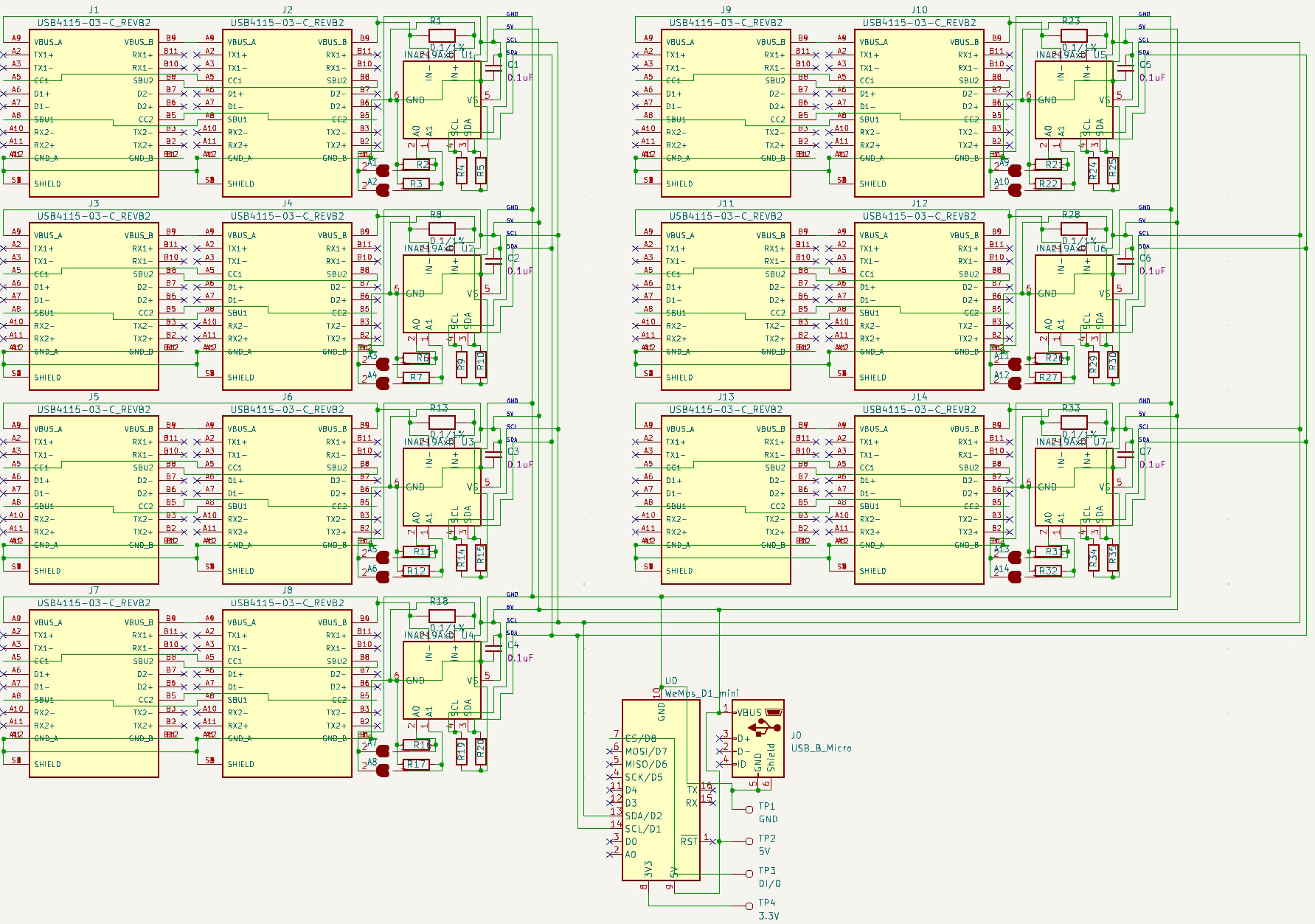
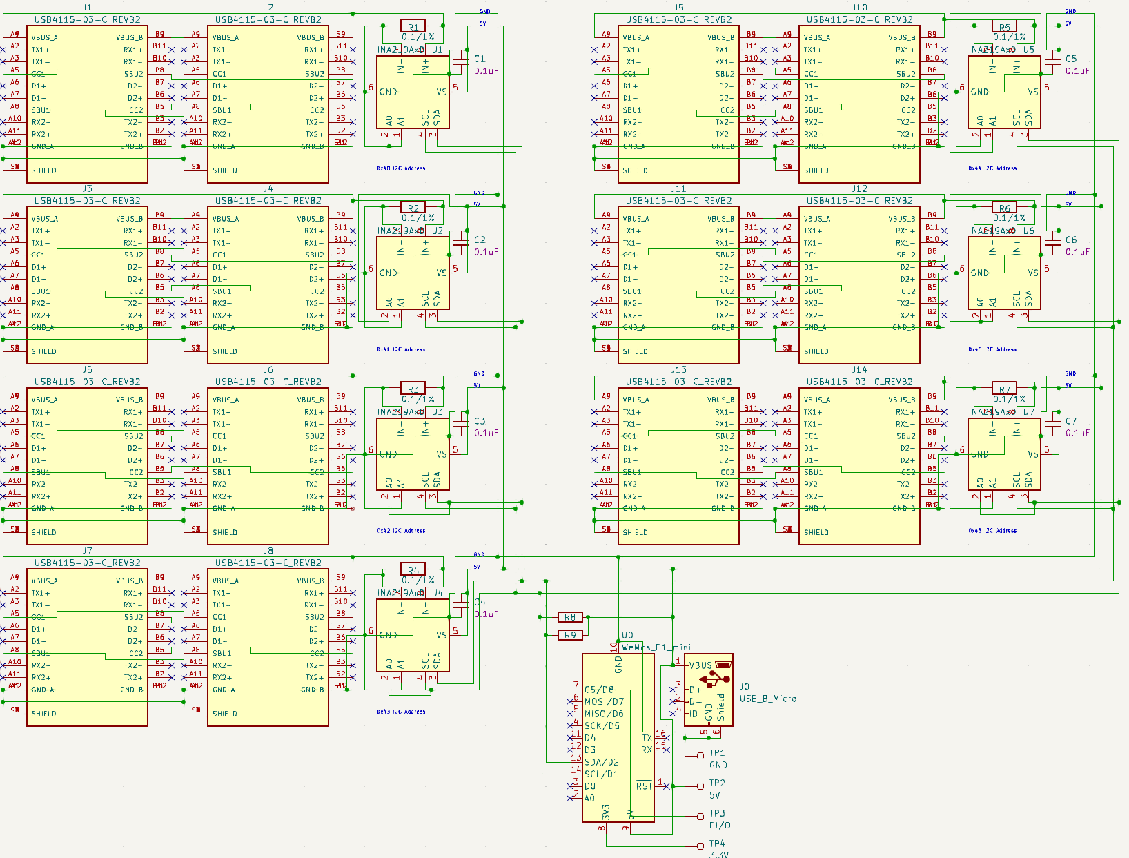
​Here is my schematic:

enter image description here

So if you can lend me a hand/knowledge or let me know if I'm even correct as-is? Maybe there's a better way of doing this?

Update #1: newer Schematic

enter image description here

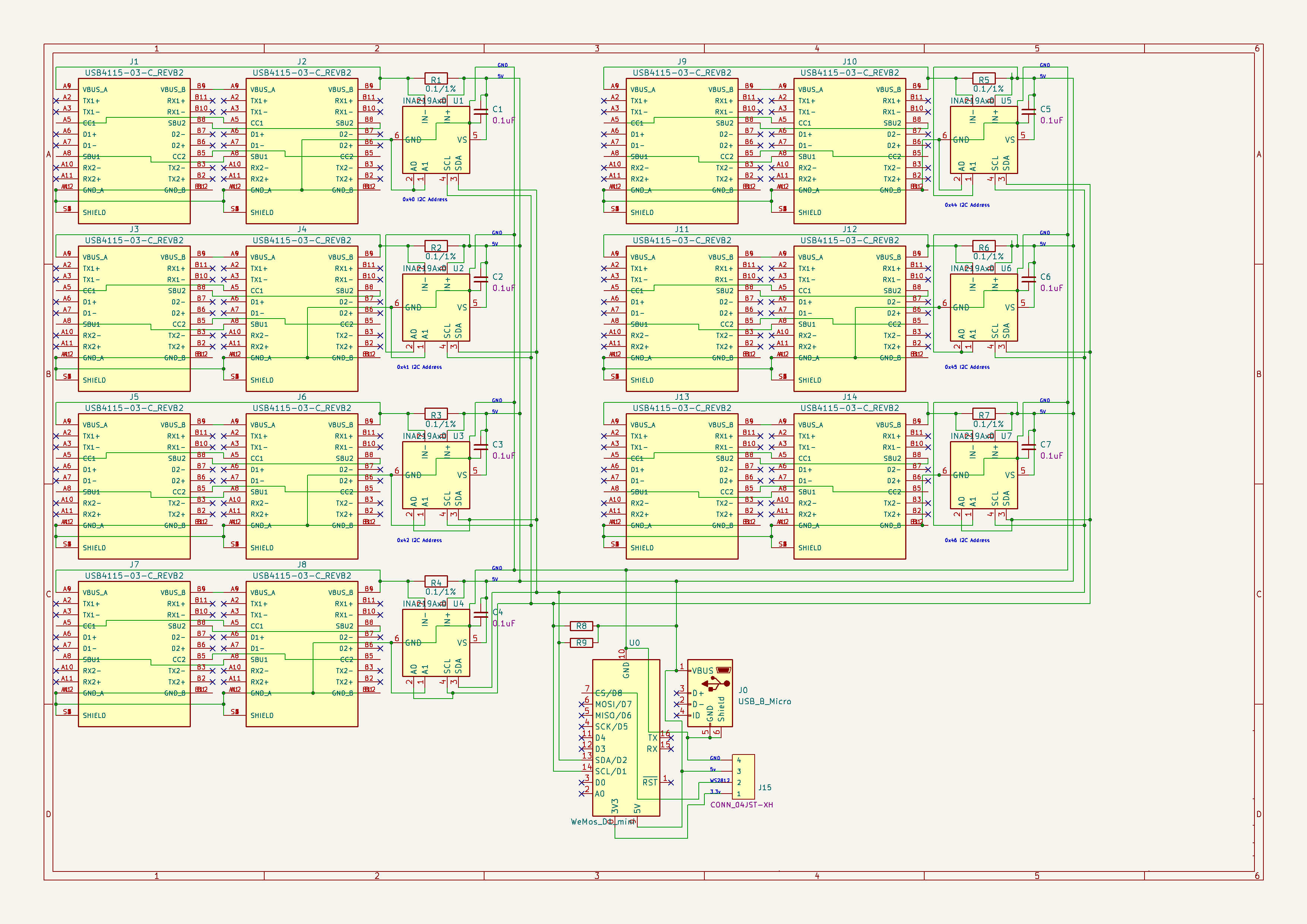
Update #2: newer Schematic

enter image description here

\$\endgroup\$
3
  • \$\begingroup\$ USB C does not support connecting 2 female receptacle together like you have done on your diagram, depending on the orientation, cable detection fails, so no charging will be performed \$\endgroup\$
    – Ferrybig
    Commented May 30, 2023 at 9:13
  • \$\begingroup\$ Please explain more @Ferrybig. Why wouldn’t it work if it’s just a pass thru? \$\endgroup\$
    – StealthRT
    Commented May 30, 2023 at 23:46
  • \$\begingroup\$ Because the cables do not connect every wire. An USB C cable purposely has a few missing connections, (called CC1/CC2 on the receptacle, CC/VCON on the plug) which is used for identification of the connected device and cable orientation. If both connected plugs are in the same orientation, the cable seems to work (while still voilating voltage drop requirements), if they are connected in flipped orientations, they do not pass this signal through. You cannot cheat this system by connecting all CC lines together in your adapter, because cables also have a resistor to identify VCON \$\endgroup\$
    – Ferrybig
    Commented May 31, 2023 at 8:18

1 Answer 1

2
\$\begingroup\$
  • you write "having the - go to ground while the + is going to the VBUS_B line", but that's not what you've drawn. The -IN pin is going to VBUS_B and the +IN pin is going to Gnd. As a result you have no way of supplying 5V power to the USB port. +IN needs to be connected to 5V.
  • your schematic and the Adafruit one you copied from have no way to select the 0x42, 0x43 & 0x46 addresses. To be able to select those addresses you need to be able to connect A0 to either SDA or SCL. To select 0x45 you need to connect both A0 & A1 to Vcc, which would be accomplished by soldering both SJ1 & SJ2 in the Adafruit schematic (and similarly in yours).
  • you have I2C pullup resistors on every one of your INA219's. That is wrong - there should only be one set of pullup resistors on the entire I2C bus and these are typically (but not necessarily) placed near the I2C master (microcontroller) device.
\$\endgroup\$
7
  • \$\begingroup\$ Thanks for catching that +/- issue. And also thank you for letting me know about the I2C resistors just needing to be used once. I have added a new schematic of these changes to my OP. \$\endgroup\$
    – StealthRT
    Commented May 29, 2023 at 19:21
  • \$\begingroup\$ Are the 2 resistors still needed on the A0/A1 lines? \$\endgroup\$
    – StealthRT
    Commented May 29, 2023 at 19:28
  • \$\begingroup\$ @StealthRT if you tie A0 & A1 directly to Vcc, Gnd, or wherever (as you've done in your update schematic), then no you do not need the resistors. They are only needed if you follow Adafruit's method where you solder the SJ jumpers to pull the pin high or leave the SJ jumpers open to let the resistor pull it low. \$\endgroup\$
    – brhans
    Commented May 29, 2023 at 22:08
  • \$\begingroup\$ @StealthRT, but you've created a new problem with the other changes you made. Your 0.1R current sensing resistors are now connected directly between Vcc and Gnd. 5V across 0.1R means that each one of those will try to draw 50A from the supply ... You should have left the USB connectors VBUS connected to the InAmp's -IN as you had it before, and connected +IN to Vcc instead of Gnd. \$\endgroup\$
    – brhans
    Commented May 29, 2023 at 22:11
  • \$\begingroup\$ A little confused as to what you are saying. Connect the + to usb vbus and - to ground? As I look at it that’s how it’s connected in the new one? \$\endgroup\$
    – StealthRT
    Commented May 29, 2023 at 23:46

Your Answer

By clicking “Post Your Answer”, you agree to our terms of service and acknowledge you have read our privacy policy.

Not the answer you're looking for? Browse other questions tagged or ask your own question.