0
\$\begingroup\$

I tried to find the correct compensation elements for a high voltage supply based on the application note https://www.analog.com/media/en/technical-documentation/application-notes/an118fb.pdf The schematic is here: enter image description here
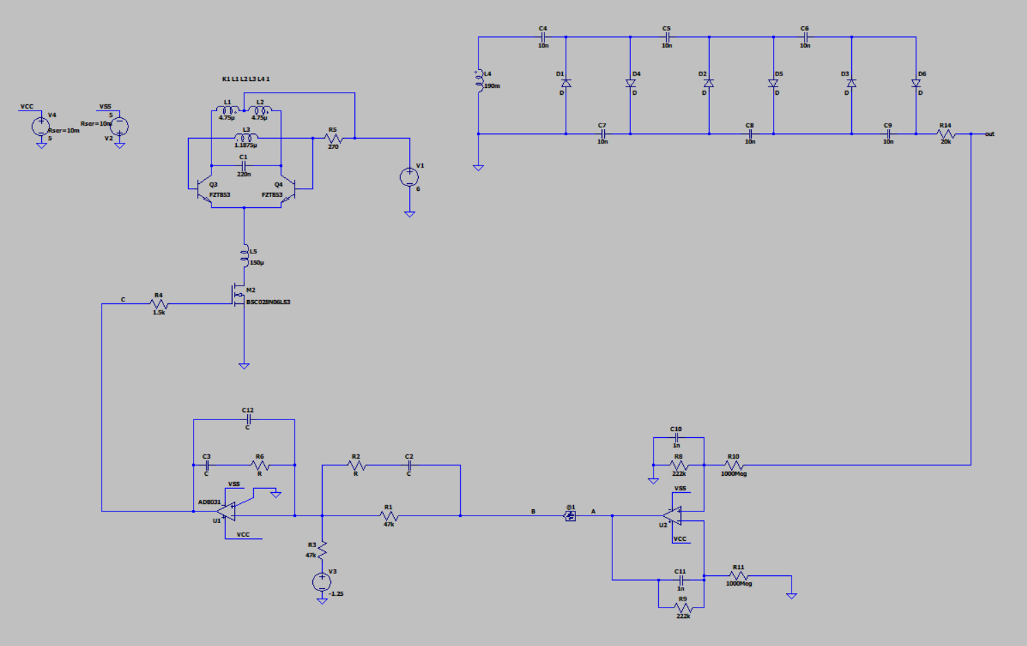
I used Bode100 to inject a test signal via a transformer across a 10R resistor placed between points A and B. I did a lot of experimenting and calculations with different compensation component values (both type II and type III). I measured the loop gain (B to A), the compensator gain (B to C) and the plant gain (C to A). The measured compensator gain always corresponded well to simulation results. Also, the plant and compensator gains added up nicely to give the loop gain.

However, when I changed the R1 to a different value (10k) and R3 too in order to keep the same division ratio, the plant gain changed with all other components left unchanged. Why? I think the plant is independent of the compensator here. The only thing I can see changed for the plant is the loading of U2 but this should be insignificant, especially at low frequencies (10Hz) where I was the plant gain change.

Any ideas why the measured plant gain changes?

EDIT:I have been tipped off the reason could be changed transfer characteristic of the MOSFET. I could be and probably am sometimes in the triode region, sometimes is the saturated region. Allegedly the triode region could be a problem in terms of stability as the MOSFET resistor-like behaviour fights the inductor L5, which act as a current source (more or less). Any opinions/insights/comfirmation on this?

\$\endgroup\$
8
  • \$\begingroup\$ I didn't see your tripler design in the app note you link. The tripler will produce a lot of time lag and will need extra special compensation to make the output stable. I'd use and output comparator with a tiny bit of hysteresis. \$\endgroup\$
    – Andy aka
    Commented Jul 18, 2023 at 14:13
  • \$\begingroup\$ @Andy aka This is called a tripler? The multiplication factor is 6. Anyway, the multiplier is not in the app note, thanks for pointing out the time lag. Yes, I am struggling with stability here. But I do not understand your idea with the comparator, what would you be comparing and how does that help stability? \$\endgroup\$
    – Hyp
    Commented Jul 18, 2023 at 14:56
  • 1
    \$\begingroup\$ Oops I meant a 6x voltage multiplier. You would compare the output voltage (a potential divided version of course) with some reference voltage and, use the comparator output to activate (or turn off) the driving circuit. Hysteresis means it won't won't go unstable around the voltage output required but, it will hunt between the hysteresis limits and create ripple. \$\endgroup\$
    – Andy aka
    Commented Jul 18, 2023 at 15:00
  • \$\begingroup\$ Oh, I see. Not sure I could get away with this ripple. Plus I'm worried about what this would do to the startup time of the oscillator. Would you have a link to where a comparator is used this way or a tip as to what to search for, I couldn't find anything. \$\endgroup\$
    – Hyp
    Commented Jul 18, 2023 at 15:18
  • \$\begingroup\$ If you turn M2 off when it reaches the required voltage on the output this should work. \$\endgroup\$
    – Andy aka
    Commented Jul 18, 2023 at 15:42

0

Your Answer

By clicking “Post Your Answer”, you agree to our terms of service and acknowledge you have read our privacy policy.

Browse other questions tagged or ask your own question.