7
\$\begingroup\$

I have:

  • one 220 V AC -> 10 V AC transformer

    enter image description here

  • one push-button switch (at the door)

  • two bells for two different places of the house; they should ring together when the (single) door push-button switch is pressed. Note: I don't want to replace the bells because I like their sound.
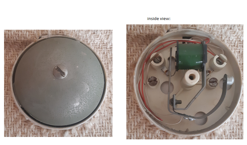
    Photo of a single bell:

    enter image description here

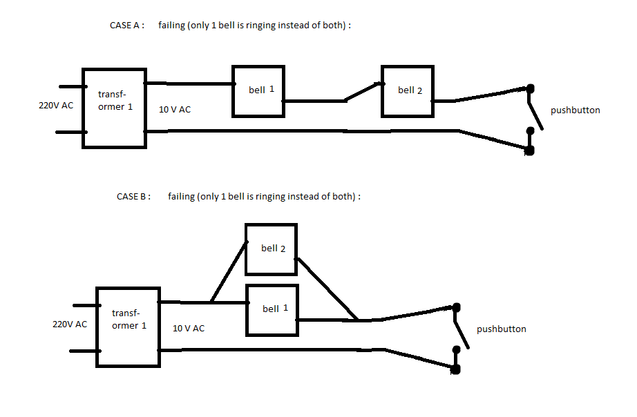
Question: Why do the 2 following solutions fail?

enter image description here

Initially, there were 2 transformers connected like this, and it worked (unfortunately, the 2nd transformer is now broken and unusable):

enter image description here

(Schematics thanks to @Transistor)

Edit:

  • with "case B" above, we have, at the output of the transformer:

    • 10.3 V AC when no bell rings
    • 7.7 V if either one of the two bell rings
    • 6.0 V if both bells are connected. Then only one bell rings.
  • close-up photo of the other bell (it seems that it is the same model) (you can click to zoom):

    enter image description here

  • when the bell is not powered, we have 15 Ohm between the two wires. When the coil armature touches the right metal part, the two wires don't seem neither shorted nor broken circuit: we still have 15 Ohm. NB: I have only been able to push the right metal by hand, and I have not been able to pull out / make the armature go out.

\$\endgroup\$
7
  • \$\begingroup\$ It looks like one transformer may not have enough power for two bells. Can you show a picture of the push button? I want to verify that it is a DPST and not a SPST. \$\endgroup\$
    – Rodo
    Commented Aug 9, 2023 at 16:55
  • \$\begingroup\$ @Rodo: this push button is not accessible, it is in the wall with no screws, etc. Can I test if it's a DPST or SPST with a multimeter? \$\endgroup\$
    – Basj
    Commented Aug 9, 2023 at 17:02
  • \$\begingroup\$ @Basj Does it have two wires or three? If it's two then it's SPST, or at least connected to act as a SPST. \$\endgroup\$
    – GodJihyo
    Commented Aug 9, 2023 at 17:06
  • \$\begingroup\$ @Basj Can you do a test with a multimeter to confirm how the bell operates? With the power disconnected can you put your ohmmeter across it and measure the resistance? Then press the armature against the coil and see if it now shows an open or short circuit. \$\endgroup\$
    – GodJihyo
    Commented Aug 9, 2023 at 17:18
  • \$\begingroup\$ Maybe for clarity you should explain whether the bell makes a "single ding" while the button is pressed, or does it make a continuous ringing sound (rapid "ding"s). It's no ding-dong bell, right? \$\endgroup\$
    – U. Windl
    Commented Aug 10, 2023 at 21:27

3 Answers 3

7
\$\begingroup\$

The first solution fails because to have two bells in series you would need twice the voltage of a single bell. The transformer is not going to supply enough voltage. Even if you had enough voltage it would probably not work because these bells work by interrupting the circuit. When the button is pressed the coil is energized and attracts the armature, which hits against the bell, at the same time there is a contact that opens breaking the circuit, this removes power from the coil, the armature is released and falls back to its original position, the contacts are closed again, and the circuit is completed starting another cycle of the bell ringing. Otherwise the clapper would just stick to the bell as long as the button was pushed. With two in series you'll have both trying to break the circuit and it's going to not work as intended.

The second solution probably fails because two bells in parallel would need twice the current of a single bell and one transformer may not be able to supply enough current.

Taking a closer look at the picture it appears as these might not actually be breaking the circuit, they might be shorting the coil which would interfere with their operation in parallel, so a higher current transformer might not solve the problem.

You can see how clapper doorbells typically work here.

Update: From your tests and additional photos it appears that this does not work like a typical electric bell. Every one I've ever seen, and every diagram I find online shows them having a set of contacts that interrupts the power to the coil to make the bell cycle. I can't see that on yours. The only thing I can think of is that they rely on the AC current's changing polarity and the dampening of the spring to make the bell ring repeatedly.

If this is the case we're back to case 1 being not enough voltage for two in series, case 2 being not enough current for 2 in parallel.

\$\endgroup\$
18
  • \$\begingroup\$ Can you please clarify your last paragraph? I don't understand it. \$\endgroup\$ Commented Aug 9, 2023 at 17:08
  • \$\begingroup\$ @DavideAndrea I think when the coil pulls the armature in it hits against that screw and shorts the coil, releasing the armature so that it cycles back and forth. It's hard to tell from the picture though. \$\endgroup\$
    – GodJihyo
    Commented Aug 9, 2023 at 17:15
  • \$\begingroup\$ @Basj If you have them in parallel and one closes, it would short them both out. With the timing on them not being exactly the same their operation is going to be sporadic. Basically you have two bells each trying to momentarily turn off the circuit and clashing with each other. See my comment on the OP about testing it to see which way it works, and the link in my answer which describes how one that breaks the circuit works. \$\endgroup\$
    – GodJihyo
    Commented Aug 9, 2023 at 17:35
  • \$\begingroup\$ "I think when the coil pulls the armature in it hits against that screw and shorts the coil,". No, it doesn't. The coil is wired to the two terminals on the base and nothing else. You are seeing long wires that are routed at the bottom of the bell: they are not connected to the mechanism. \$\endgroup\$ Commented Aug 9, 2023 at 17:54
  • \$\begingroup\$ @Basj When you push the button it magnetizes the coil and pulls in the armature to hit the clapper against the bell, at the same time it cuts power to the coil so that the armature comes back, it can do this either by opening the circuit or shorting out the coil. I can't tell for sure from the picture which it is but it looks more like it's shorting. \$\endgroup\$
    – GodJihyo
    Commented Aug 9, 2023 at 17:57
5
\$\begingroup\$

Circuit "Case B" is correct. If one bell is not ringing, it's because the transformer is not powerful enough to power both bells, the voltage sags, and only one bell is able to ring at a lower voltage. Either that, or there is an error in your wiring.

\$\endgroup\$
8
  • 1
    \$\begingroup\$ Thanks @DavideAndrea. Is there a polarity to respect to connect both bells in parallel? (Looking at the photo of the bell, I can see a coil in the bell, I don't know if it changes anything in respect to polarity) \$\endgroup\$
    – Basj
    Commented Aug 9, 2023 at 17:22
  • \$\begingroup\$ " Is there a polarity"? No. They are AC. AC is not polarized. \$\endgroup\$ Commented Aug 9, 2023 at 17:53
  • \$\begingroup\$ Thanks @DavideAndrea. I thought that, if too much current is drawn from one single transformer, then it would heat a lot, but still it would work, at least for a couple of seconds. Here with one single transformer + two bells in parallel, only one bell rings, that's strange. Don't you think both should still work during a few seconds (+ massive heating if too much current is drawn from the transformer)? \$\endgroup\$
    – Basj
    Commented Aug 9, 2023 at 22:30
  • 2
    \$\begingroup\$ Across the transformer terminals. Compare the voltages with no bells, one bell, and two bells connected. \$\endgroup\$ Commented Aug 9, 2023 at 23:40
  • 3
    \$\begingroup\$ Another experiment you can do: With case B switch the bells around. If the same bell rings both times then the other bell may be faulty, if a different bell rings each time then there may be a problem with your wiring. Neither of these is conclusive mind you, but it's a simple test. \$\endgroup\$
    – Turksarama
    Commented Aug 10, 2023 at 1:13
3
\$\begingroup\$

Wiring the bells in series will divide the available voltage by 2 so each bell receives only 5 V, insufficient to operate.

Wiring the bells in parallel overloads the class 2 (Canada) transformer which pulls the transformer voltage too low, insufficient to operate.

The original wiring with two transformers is the correct (only?) way to make both bells work with the same key-press.

You will have to replace the defective transformer with a new one.

Be certain to follow local electrical codes. Check with an electrician if you are uncertain.

\$\endgroup\$
6
  • 2
    \$\begingroup\$ The OP said the output voltage of the transformer is 10VAC not 24VAC \$\endgroup\$
    – Rodo
    Commented Aug 9, 2023 at 17:01
  • 2
    \$\begingroup\$ Oops, it is fixed \$\endgroup\$
    – user319836
    Commented Aug 9, 2023 at 17:05
  • \$\begingroup\$ Thanks! overloads the class 2 (Canada) transformer what is a class 2 (Canada) transormer. Do you think mine is such a transformer ? pulls the transformer voltage too low : how to check this with a multimeter? \$\endgroup\$
    – Basj
    Commented Aug 9, 2023 at 17:13
  • 1
    \$\begingroup\$ Class 2 transformers can be shorted and not fail or cause a hazard. All doorbell transformers are like this (at least in Canada). They are marked as such. I don't know the equivalent in other countries. Check with an electrician to be sure. For doorbell application, you can refer to them as a doorbell transformer. \$\endgroup\$
    – user319836
    Commented Aug 9, 2023 at 17:20
  • 2
    \$\begingroup\$ "If I have a more powerful transformer,": Depends on your local electrical code. If allowed, then David Andrea's answer is correct. \$\endgroup\$
    – user319836
    Commented Aug 9, 2023 at 17:27

Your Answer

By clicking “Post Your Answer”, you agree to our terms of service and acknowledge you have read our privacy policy.

Not the answer you're looking for? Browse other questions tagged or ask your own question.