0
\$\begingroup\$

In a previous setup, I had two doorbells, each one with its own 10V AC transformer, as detailed in Why is it impossible to connect these two doorbells in series or parallel?.

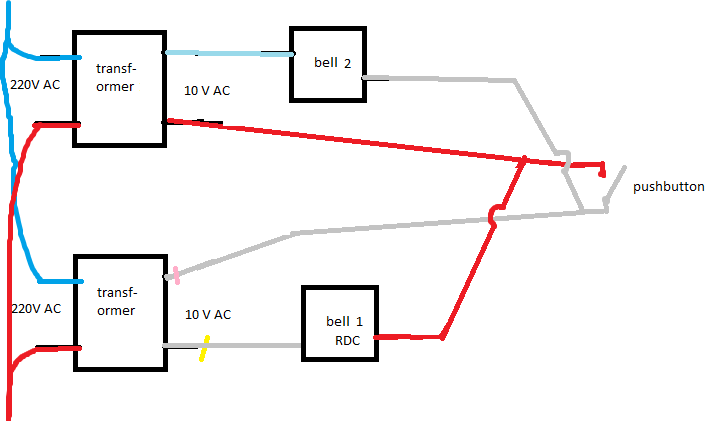
I now know it was connected this way:

enter image description here

Question: it was probably like this during decades, but was it safe? It seems that when the pushbutton switch is closed, one output of a transformer was connected to an output of the second transformer, but probably in phase opposition. Is this a problem?

I'm asking this question, because I need to re-do a similar setup with two 220 V AC => 10 V 1C transformers.

\$\endgroup\$

1 Answer 1

6
\$\begingroup\$

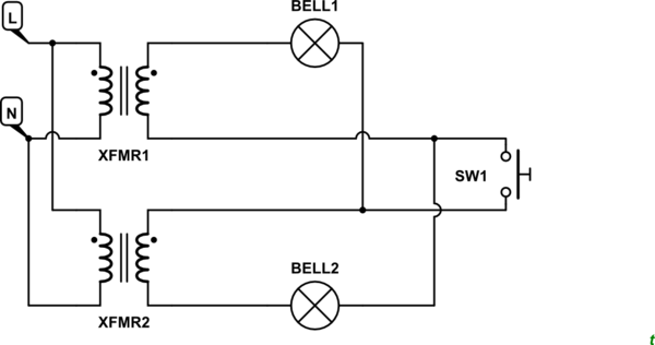
schematic

simulate this circuit – Schematic created using CircuitLab

Figure 1. Original circuit redrawn using the built-in CircuitLab editor.
schematic

simulate this circuit

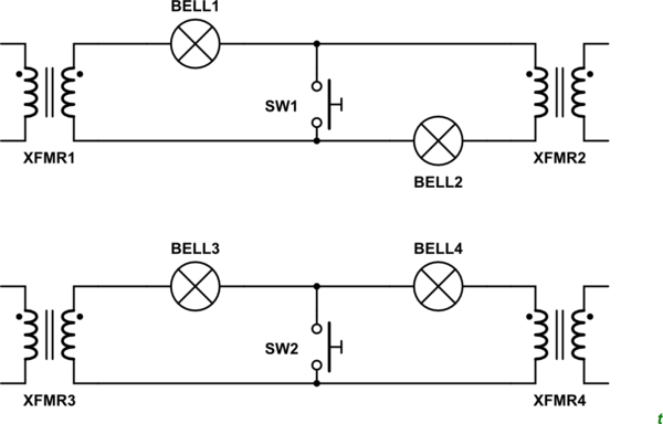
Figure 2. Redrawn with mains wiring removed for clarity.

Figure 3. Electrical equivelant circuit for even more clarity.

  • If the two transformers' polarity matches as shown in Figure 2 and 3, and the output voltages are the same then no current will flow through the bells as there is no voltage (potential) difference across them.
  • When SW2 is pressed both bells will have a return path to their respective transformers.
  • If the transformers are wired in anti-phase (either on the mains side or on the low-voltage side) both bells will ring continuously.

The circuit is safe but very unusual.


From the comments:

  1. Given that two transformers never have perfectly the same output voltage, does this mean that probably some (little) current flows permanently in the bells (perhaps ~0.5 V), even if the button is not pressed? Is this a problem?

Yes, a little current will flow.

It could be a problem if it's enough to heat the coil given that it would be on continuously. You could tell by touch.

  1. How can we know that each bell's return path is its own respective transformer, and that the current doesn't flow to the other transformer?

Since current flows in a loop what leaves the top terminal on each transformer must return on the bottom terminal. Technically the mobile charge carriers (electrons in the case of metallic conductors) could cross over but the quantity in each branch would remain correct.

\$\endgroup\$
7
  • \$\begingroup\$ Thanks a lot! 1) Given that 2 transformers never have perfectly the same output voltage, does this mean that probably some (little) current flows permanently in the bells (perhaps ~0.5 V), even if the button is not pressed? Is this a problem? 2) How can we know that each bell's return path is its own respective transformer, and that the current doesn't flow to the other transformer? \$\endgroup\$
    – Basj
    Commented Aug 9, 2023 at 22:13
  • \$\begingroup\$ Which better/more usual solution would be recommend @Transistor? Either with one single transformer (strangely it didn't work when I tried, see the linked question), or with 2 transformers? \$\endgroup\$
    – Basj
    Commented Aug 9, 2023 at 22:15
  • \$\begingroup\$ See the update. Two bells may overload one transformer and the voltage might collapse. A two-pole switch would allow you to maintain independence between the two circuits - but that would be unusual for a bell-push. \$\endgroup\$
    – Transistor
    Commented Aug 9, 2023 at 22:20
  • \$\begingroup\$ Thanks @Transistor. I cannot change the switch for now, and there is just one circuit (no independence). Two bells may overload one transformer and the voltage might collapse: I thought that, if too much current is drawn from one transformer, then it would heat a lot, but still it would work, at least for a couple of seconds. Here it doesn't work at all with one single transformer + two bells in parallel, that's strange! (only one bell rings). Photo of the bell: i.sstatic.net/IRctV.png \$\endgroup\$
    – Basj
    Commented Aug 9, 2023 at 22:28
  • 1
    \$\begingroup\$ Ah! CircuitLab generates a PNG image for the schematic and StackExchange allows me to resize the images by adding an 's', 'm' or 'l' for small, medium or large, and that breaks the link. I'll resize another way. Try the simulation links again in a minute. \$\endgroup\$
    – Transistor
    Commented Aug 10, 2023 at 17:24

Your Answer

By clicking “Post Your Answer”, you agree to our terms of service and acknowledge you have read our privacy policy.

Not the answer you're looking for? Browse other questions tagged or ask your own question.