3
\$\begingroup\$

I'm on a quest to have an iPhone wallet case that supports wireless charging. I won't bore you with my long list of failures, but would love feedback on this strategy.

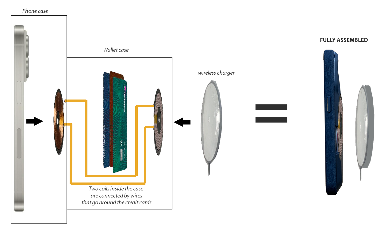
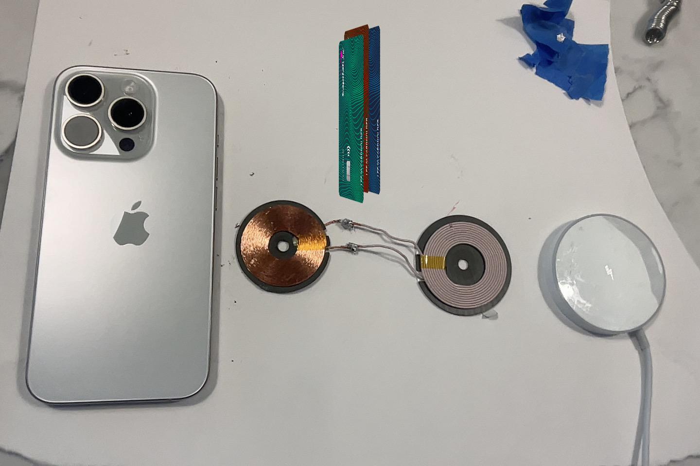
I 3d printed a case which puts a coil on the back of the phone, wired around my credit cards, to a coil on the outside of the case. My theory is that the outer coil would relay the charger's current to the coil near the phone - which would charge the phone. I've tried many configurations, chargers, orientations, etc - but it does nothing.

Is this even theoretically possible? Or am I in crazy town?

  • Maybe it's a resonance issue?
  • Maybe the coils need to be the same size?
  • I know the iphone does a handshake before power transfer - maybe that's the issue?

enter image description here

The coils are taken from a wireless charger and receiver and I could not find a schematic from the manufacturer. It just says 5 Volts, 2 amps, 10 watts. I used a voltage meter to verify that both are able to receive power from a wireless charging puck.

End goal is that my wallet sits between the charger and the phone. Here's what my device is supposed to look like:

enter image description here

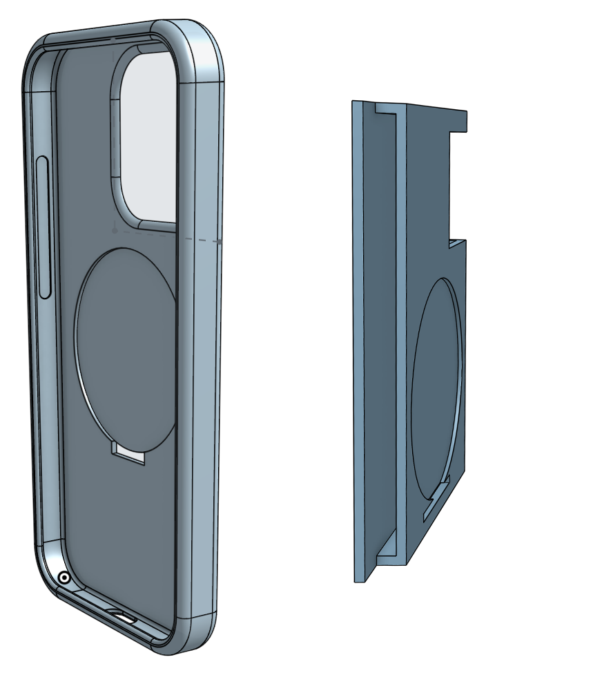
In case it's helpful, here are the case designs. It's printed in TPU as two separate pieces that will be glued together.

enter image description here

\$\endgroup\$
3
  • 1
    \$\begingroup\$ How about a circuit diagram or better, a schematics? \$\endgroup\$
    – MiNiMe
    Commented Oct 29, 2023 at 21:00
  • 1
    \$\begingroup\$ And maybe a rough picture of what the device is supposed to look like that you're building. I totally don't get what you are trying to build. Inductive charging phone. Okay. With your wallet? Is there a Batterypack in it? Or do you want to put your wallet in-between the charger and the phone? What? \$\endgroup\$
    – S_G
    Commented Oct 30, 2023 at 7:42
  • \$\begingroup\$ You get too much loss. It's bad as it is, then another coil and gap. I'd spend my money on grab and place the existing coil at the back of the case, and find a way for cabling into the phone. \$\endgroup\$
    – MiNiMe
    Commented Oct 31, 2023 at 19:17

1 Answer 1

1
+100
\$\begingroup\$

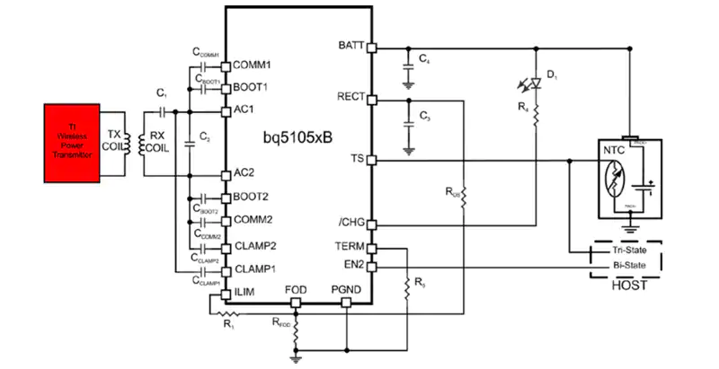
A charger circuit looks like this:

enter image description here

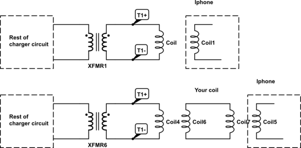
So in theory yes you should be able to do this:

schematic

simulate this circuit – Schematic created using CircuitLab

Consider these things:

  1. You have two air gaps in your design this is going to reduce efficiency significantly. The air gaps could also affect detection, try and eliminate the gaps.

  2. You need to build your coil in such a way that the transfomer is 1:1 and it has sufficient bandwidth to pass ~100kHz

  3. The coils will interfere with each other, for starters I would probably start out with the coils side by side (not inline) so that vertical magnetic fields don't interfere. Once you get this working you could try a vertical configuration like in your diagram

  4. The datasheet of the bq5105 should be helpful, you could potentially get a evaluation kit and see if there is an option to force the coil to stay in trasmit mode which would make it much easier for testing. The Qi standard does have foreign object detection so this could also be getting in the way of your goal.

\$\endgroup\$

Your Answer

By clicking “Post Your Answer”, you agree to our terms of service and acknowledge you have read our privacy policy.

Not the answer you're looking for? Browse other questions tagged or ask your own question.