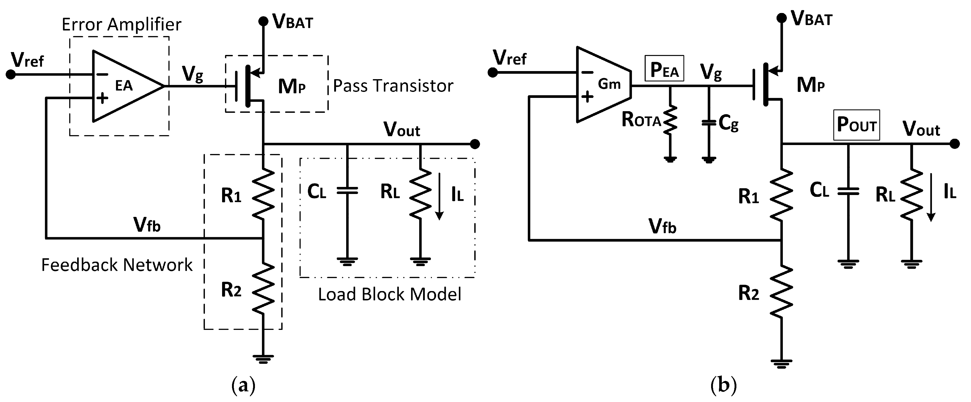
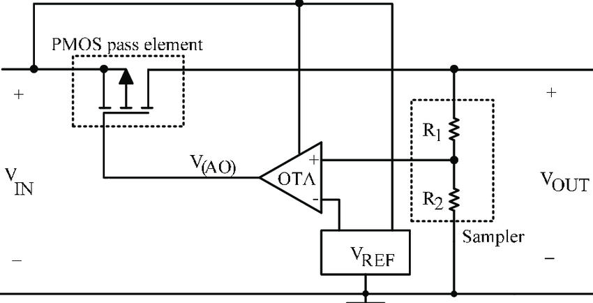
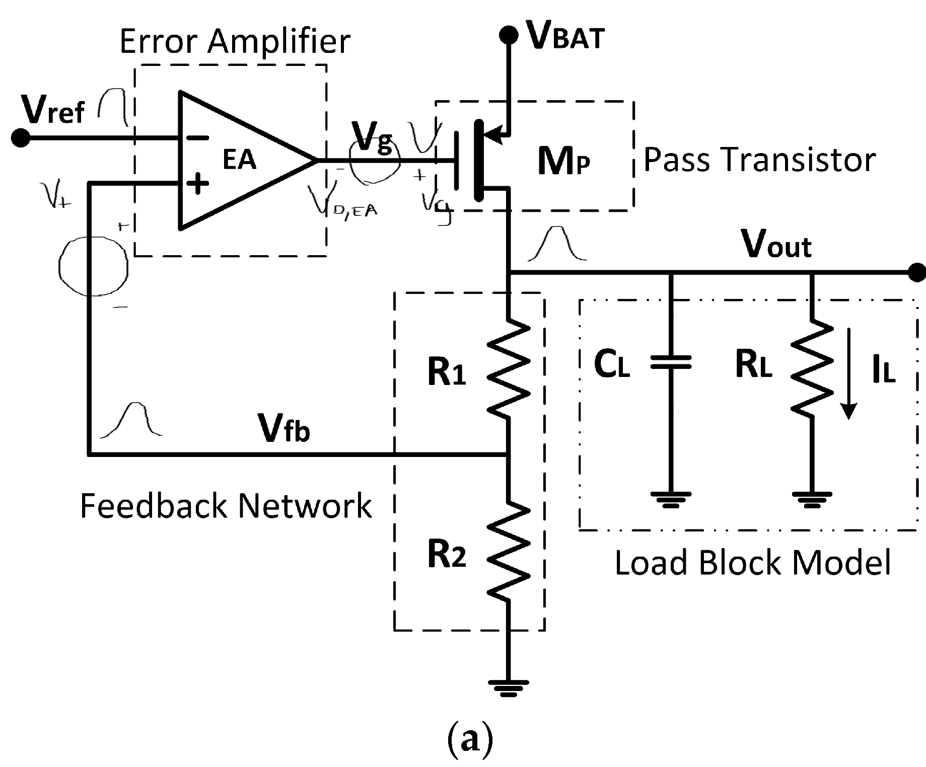
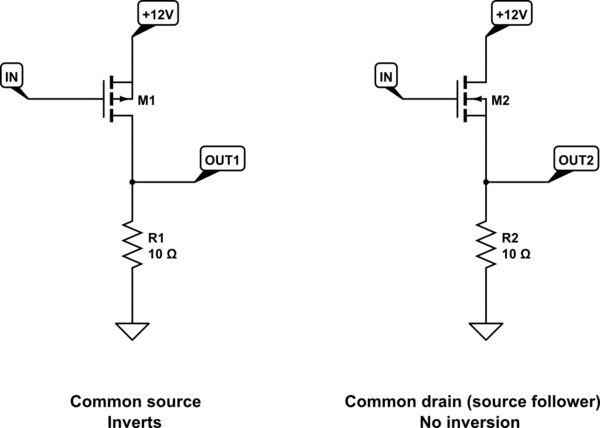
These two circuits look very similar, but the one on the left inverts, and the one on the right does not invert:
simulate this circuit – Schematic created using CircuitLab
On the left is a "common source" setup, using a P-channel MOSFET, whose output (taken at the drain) is inverted with respect to the input at the gate. That is, as IN rises in potential, OUT1 falls, and vice versa.
On the right we have a common drain configuration, otherwise known as a "source-follower", employing a N-channel MOSFET. The word "follower" in the name suggests that the MOSFET's source (the output here) "follows" the input at the gate, implying that there's no inversion. In other words, a rise in potential at IN will result in a rise at OUT2. Conversely, if IN decreases, so does OUT2.
I explain this distinction in much greater detail in this answer.
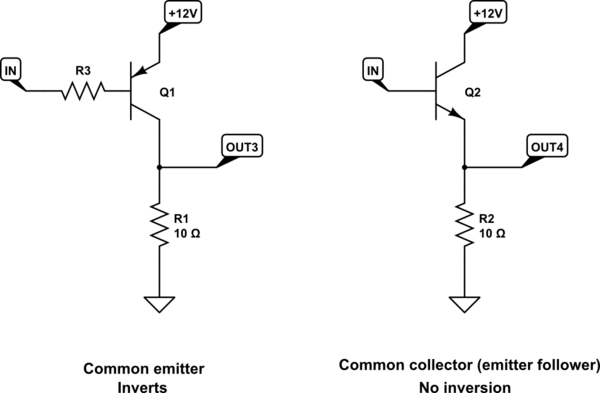
The same difference in behaviour can be observed in bipolar transistor circuits, where inversion occurs in the "common emitter" arrangement, but not in "common collector" (also called "emitter follower"). The distinction is in where you derive the output signal. For the common emitter circuit, the output is the collector, and is inverted with respect to the signal input at the base, whereas the the emitter-follower does not invert:
simulate this circuit
You'll notice that in all those circuits where you identified feedback returning to the non-inverting input, which seems to contradict how we usually implement negative feedback using the inverting input, feedback is derived from the drain of the transistor stage, which implies there's an inversion from that stage. They all use "common source" stages.
To obtain negative feedback, the goal is to have the op-amp output change in a manner that decreases the overall output, as that output rises. That is, the op-amp must oppose any change in overall output. If feedback were taken directly from the op-amp's own output, then that feedback must be applied to the op-amp's inverting input, so that a rise in output would result in the op-amp opposing that very rise, and vice versa.
However, in these circuits, due to the inverting action of the transistor stage, the overall output actually rises as the op-amp's output falls (and vice versa), and so to produce negative feedback that overall output must be coupled back to the op-amp's non-inverting input instead.
If there's an inverted relationship between op-amp output and overall output, which happens in all these examples due to the inverting transistor stage, then you must also reverse the op-amp's behaviour, by applying feedback to the non-inverting input instead. Otherwise feedback would be positive, in which a slight rise (or fall) of overall output would result in a further rise (or fall) in overall output, causing a much larger rise (or fall), and so on, running off to some extreme.
If you inserted another inverting stage (using an additional transistor or op-amp) between the existing op-amp and transistor stages, then you could once again apply feedback to the inverting input, as you would in classic amplifier designs. That's because the overall output, and the op-amp's output would once again be back "in phase".
If you replaced the common-source transistor stage with a common-drain stage instead, then again there would be no inverted relationship between op-amp and overall output, and you would also apply feedback (as usual) to the op-amp's inverting input.
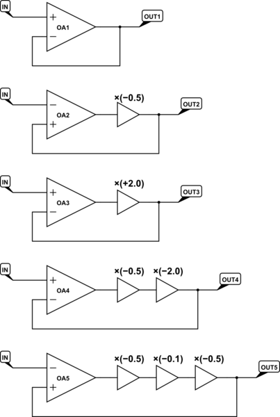
Here are some stable systems successfully employing negative feedback. Note the number of inverting stages in the path between op-amp output and overall output, and see how an odd number of inversions requires feedback to be applied to the non-inverting input:
simulate this circuit
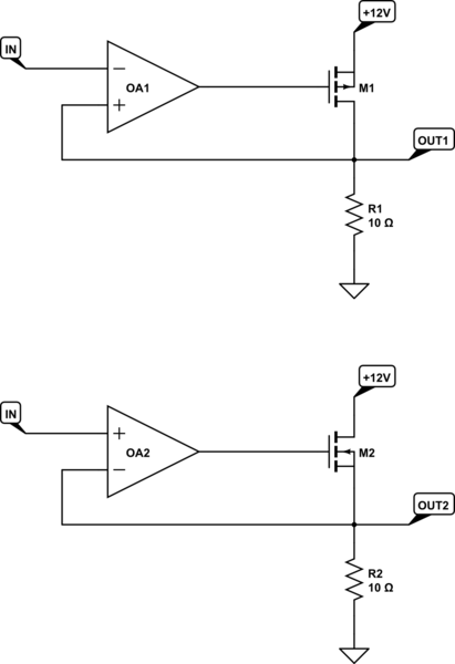
In both circuits below we successfully employ negative feedback, but the difference between them is really subtle:
simulate this circuit
Hopefully you noticed that the bottom transistor is configured as a source follower, which does not invert, and therefore feedback is applied to the inverting input, as usual. However, the top transistor is common source, that feedback signal is inverted with respect to the op-amp's own output, and overall output must be fed back to the non-inverting input for that feedback to be negative.

