2
\$\begingroup\$

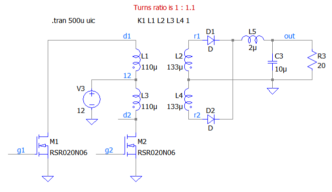
I wish to check the flux through a transformer core in my LTspice simulation. I have set up a push-pull converter simulation using a transformer with a turns ratio of 1 : 1.1, a supply voltage of 12 V and two FETs pulling either side low for almost 1 µs in turn. There is a small dead time of 50 ns, where neither of the FETs are conducting.

enter image description here

In order to determine the flux in the core, I know of two tentative approaches:

  • Determine the product of inductance \$L\$ and current \$I\$ for each winding and sum them: $$\Phi_1(t)=\sum_i^\text{windings}{L_i\cdot I_i(t)}$$
  • Measure the volt-second integral normalized by the turns ratio \$N\$ of the windings and sum them: $$\Phi_2(t)=\sum_i^\text{windings}\int_0^t{\frac{V_i(\tau)}{N_i} \text d\tau}$$

So, I set up two bv sources in LTspice to calculate each of the two expression: enter image description here
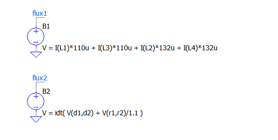
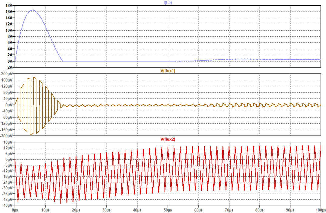
I know that the absolute turns count is missing in the second expression, only the turns ratio is respected. So it should be wrong by a constant scale factor. However, what I see is that both expressions yield qualitatively different results, which are plotted below.

enter image description here

Question

Which of these two expressions (if any) is correct and why is the other one (or both) wrong?

\$\endgroup\$

3 Answers 3

0
\$\begingroup\$

The flux in the transformer core can be assumed as the integral (over time) of the voltage at the inner winding, divided by the number of its turns. So the expression for the voltage should taking only one of the windings.

\$\endgroup\$
4
  • \$\begingroup\$ The load currents are opposite in sign in primary and secondary windings, so they are automatically cancelled in the first expression. \$\endgroup\$
    – tobalt
    Commented Nov 22, 2023 at 20:00
  • \$\begingroup\$ True! I didn't notice! I'll update the answer according to your comment @tobalt. \$\endgroup\$ Commented Nov 22, 2023 at 20:11
  • \$\begingroup\$ So the expression for the voltage should taking only one of the windings. - This comes indeed close to what I figured after many tests. It doesn't matter which of the windings one uses. One could use the one given in datasheets with its corresponding uVs rating, or for a custom transformer, one could use any winding and divide by number of turns to obtain the actual Webers in the magnetic core. \$\endgroup\$
    – tobalt
    Commented Dec 18, 2023 at 19:31
  • \$\begingroup\$ @tobalt, assuming a transformer with concentric windings, the inner winding will always reflects the flux in the core, while in the outer windings the flux (while under load) will be the sum of the core flux and the stray flux between both windings (although under no-load, as the stray flux is zero, it will reflect the core flux as well). \$\endgroup\$ Commented Dec 19, 2023 at 12:39
3
\$\begingroup\$

None of them is correct.

flux1 looks more reasonable because flux2 uses unswitched windings as well.

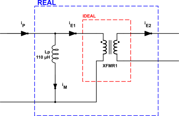
Remember the transformer model:

schematic

simulate this circuit – Schematic created using CircuitLab

The current you are measuring in the simulation is \$i_P\$ which includes energy-related currents \$i_{E1}\$ and \$i_{E2}\$, and the magnetisation current \$i_M\$ therefore \$i_P = i_M + i_{E1}\$.

Magnetisations caused by energy-related currents cancel each other therefore all that is left is the magnetisation caused by \$i_M\$.

So you should use either the L-I product or the Volt-seconds product for the primary winding only.

$$ v_p = L_p \ \frac{di_M}{dt} = N_p \ A_e \ \frac{dB}{dt} $$

So

$$ B=\frac{1}{N_p \ A_e}\int v_p \ dt = \frac{L_p}{N_p \ A_e}\int di_M $$

\$\endgroup\$
3
  • \$\begingroup\$ My first expression does cancel the "energy related" currents though. The secondary load current is opposite in sign to the primary load current. So does it mean that Equation 1 is correct? \$\endgroup\$
    – tobalt
    Commented Nov 22, 2023 at 19:58
  • 1
    \$\begingroup\$ @tobalt That's correct in principle. For LTspice, the positive current direction is from the no-dot end to the dot end. Considering the switching of each half-primary and the phases of each winding, the current directions look correct. So this makes flux1 reasonable. But still lacks scaling coming from \$A_e\$ and/or \$N_p\$. You want to measure the flux which is \$\Sigma \Phi=\Sigma B \ A_e\$, but the volt-seconds or L-I product gives you \$\Delta \Phi\$ (or \$\Sigma \Phi\$ if you sum all of them) scaled by the number of turns, \$N_p\$. \$\endgroup\$ Commented Nov 22, 2023 at 20:33
  • \$\begingroup\$ That was it! If I scale the terms in the first expression each by division with their turns ratio, then the results become qualitatetively identical, between the two expressions. Ironically, this implies that equation 2 was actually right all along, albeit one shouldn't sum all the windings. Rather, the terms for all the windings are the same anyway, so looking at any one winding with the second approach seems valid. \$\endgroup\$
    – tobalt
    Commented Nov 22, 2023 at 20:43
1
\$\begingroup\$

Which of these two expressions (if any) is correct and why is the other one (or both) wrong?
Both are wrong...

The flux in a transformer core is due to the magnetization current supplied by the primary-side voltage. It is exclusively load independent (for most reasonable analytical situations) so, measuring secondary currents and voltages (that result in \$\Phi_2\$) are not inapplicable to measuring core flux density.

In other words, the flux in a transformer core is due to the applied voltage at the driven winding (what we normally call the primary winding) and, you might as well (for your experiment) use a VCVS from the primary voltage driving an inductor of value 110 μH and look at the waveform.

Alternatively, unload the output (C3 and R3 disconnected) and use the \$\Phi_1\$ measurement. Please remember to discuss any changes to your question (that you think are needed) as a result of any answers given.

\$\endgroup\$
5
  • \$\begingroup\$ I follow your reasoning. And based on it, I conclude that the second expression is wrong because it includes also Vs integrals from "undriven" windings. However, the first expression should cancel loading effects because primary and secondary load-related currents are opposite in sign, so only the magnetization current should be left in expression 1, no? \$\endgroup\$
    – tobalt
    Commented Nov 22, 2023 at 20:04
  • \$\begingroup\$ @tobalt that sounds reasonable providing the signs are connect (easy to get in a muddle over signs) but, by the looks of it you have got your dots in the right place and, assuming that LTspice determines current direction using dots then it should be OK. I don't use LTS so I can't be sure. \$\endgroup\$
    – Andy aka
    Commented Nov 22, 2023 at 20:10
  • \$\begingroup\$ Yes the sign of currents has a fixed relation to the dots. I will check if I can make the two equations agree based on your discussion of the issues with the second approach. \$\endgroup\$
    – tobalt
    Commented Nov 22, 2023 at 20:12
  • \$\begingroup\$ I found that it doesn't matter which of the windings I use in expression 2. They all yield the same result. So summing over all 4 windings just replicates quadruple the values. I guess it makes sense. One should use a winding in approach 2, it doesn't matter whether it is a driven one or not. With Rohat's explanation, I could also make the first expression agree with expression 2. (A scaling by turns ratio is missing in expression 1) \$\endgroup\$
    – tobalt
    Commented Nov 22, 2023 at 20:47
  • \$\begingroup\$ @tobalt I have no idea what you are talking about because it's the magnetization current that gives flux so considering a more complex equation that what is necessary is just over-complicating things without a sensible reason. \$\endgroup\$
    – Andy aka
    Commented Nov 22, 2023 at 21:05

Your Answer

By clicking “Post Your Answer”, you agree to our terms of service and acknowledge you have read our privacy policy.

Not the answer you're looking for? Browse other questions tagged or ask your own question.