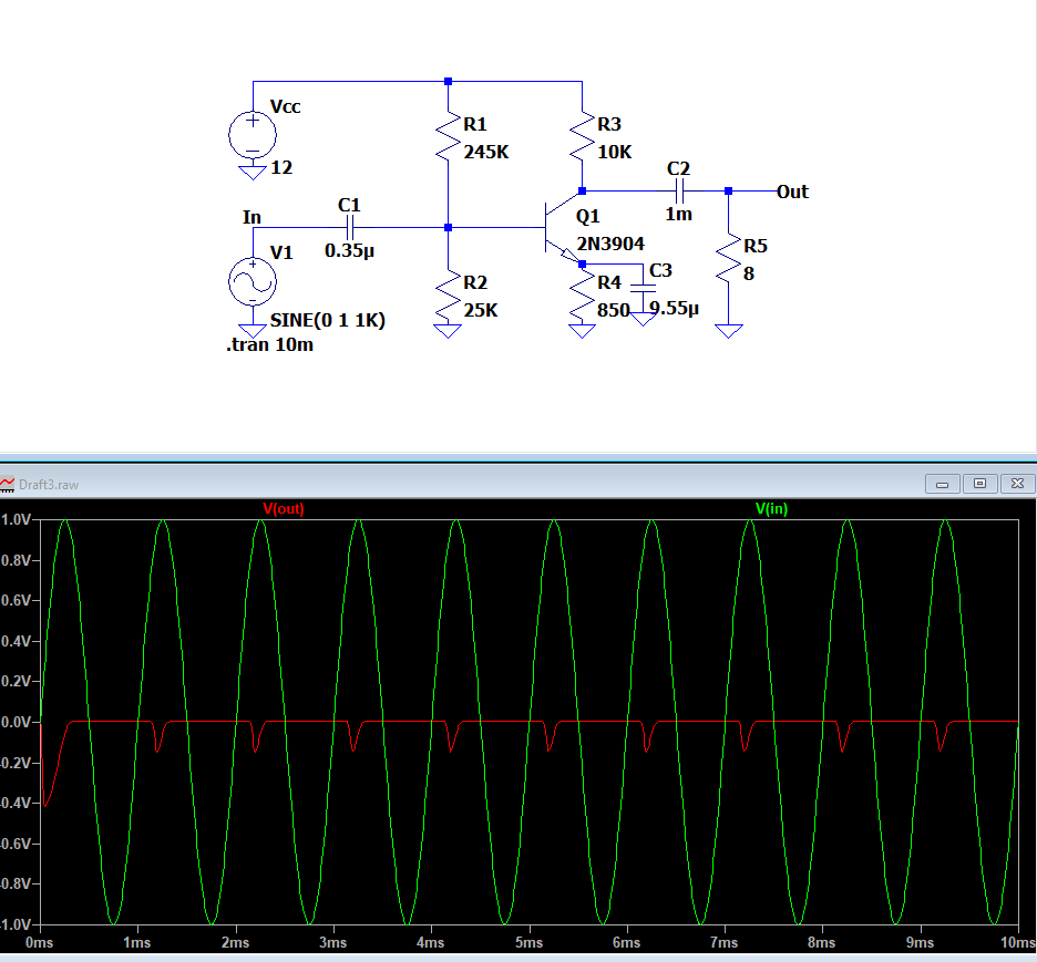
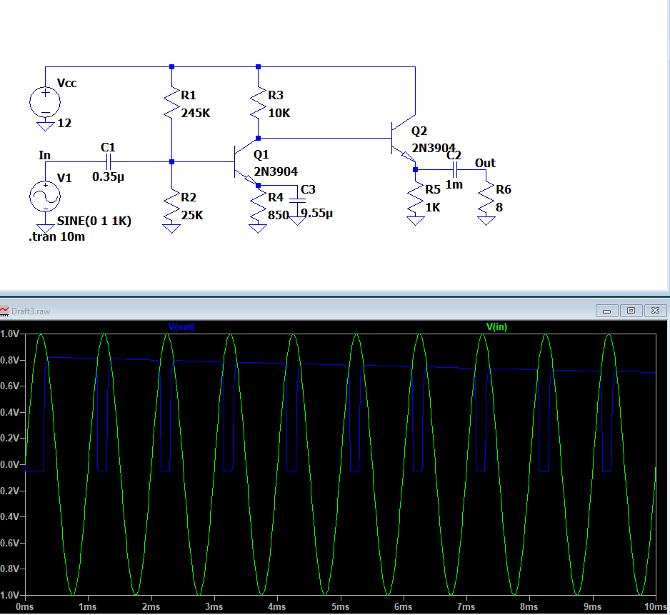
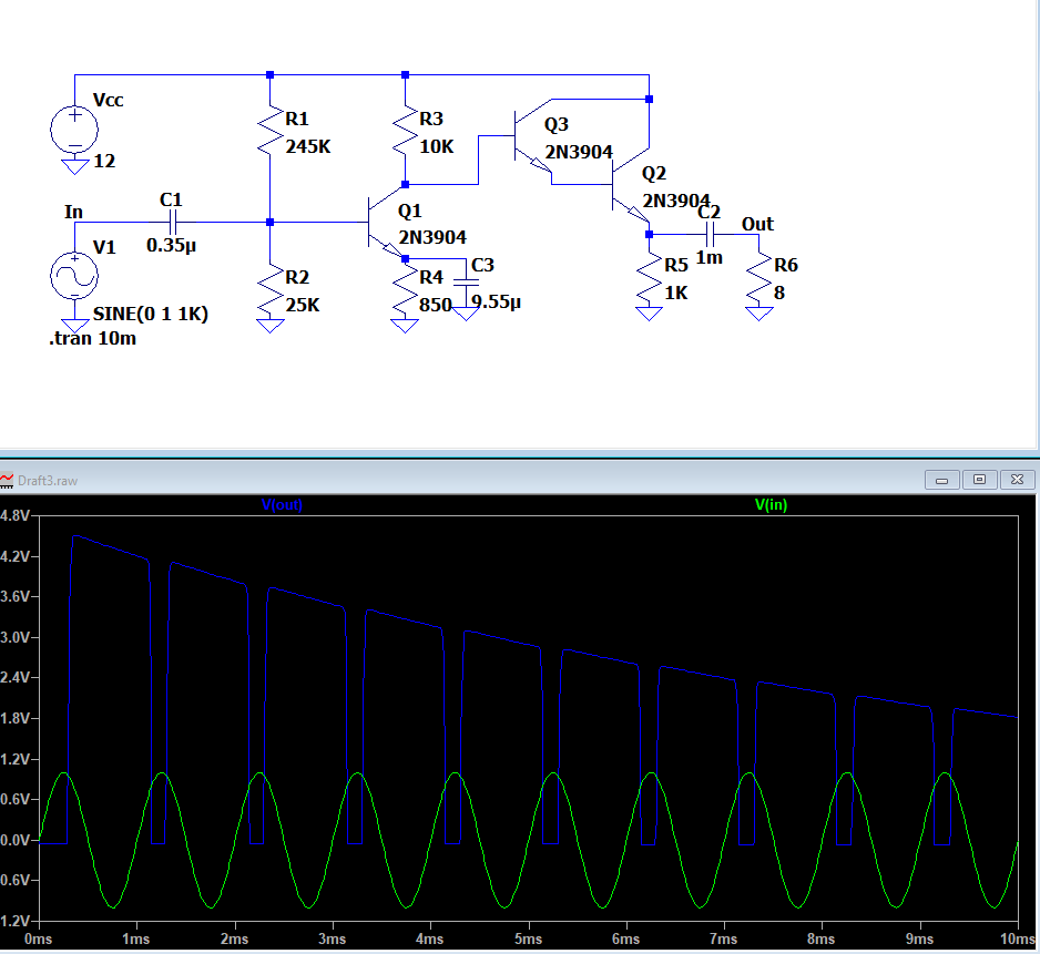
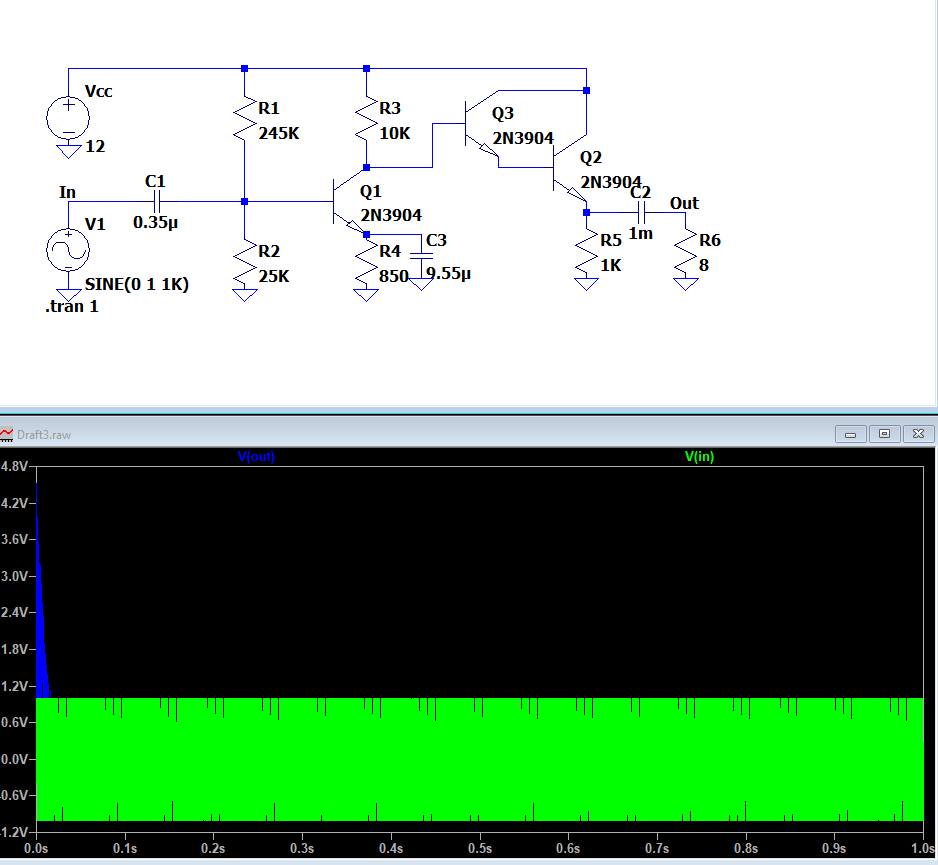
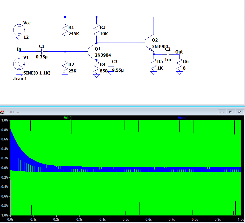
I sincerely wish you'd give up on the 2nd stage -- the power output stage -- that you keep insisting on using. It's useful if and only if you want lots of heat and/or fire and/or a rapid unplanned/unscheduled disassembly.
The 2nd stage is not salvageable. So I'm not wasting more time on it. You can read something I wrote, recently, here.
It's just wrong. Abandon it.
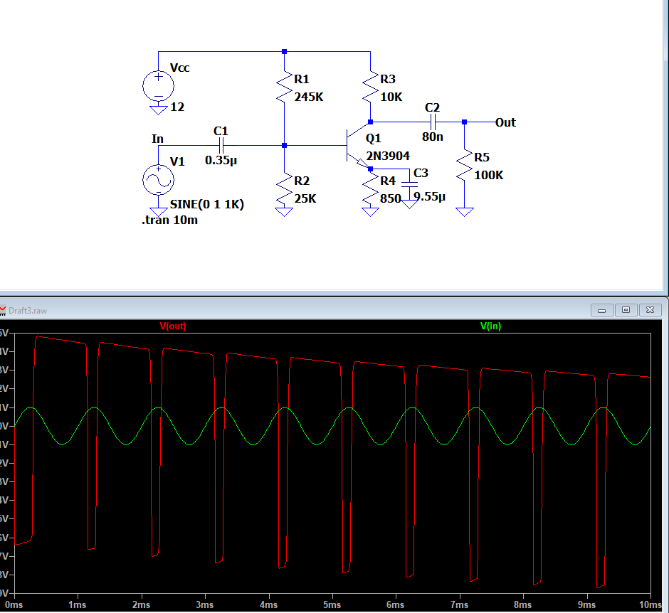
On the first stage, the main problem is that it is highly distorting, due to a widely variable voltage gain that depends upon the applied signal, itself.
Let's first look at the DC bias operating point (quiescent operation):
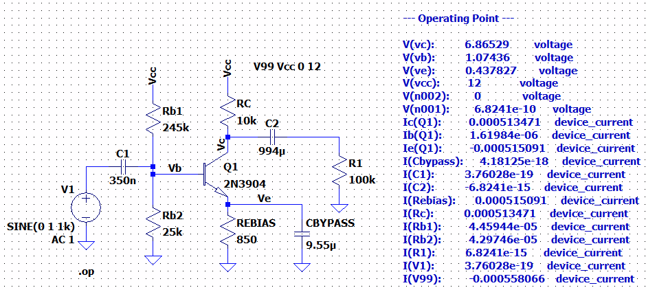
From that, and the emitter bypass capacitor arrangement, I can estimate the small signal voltage gain as about \$45\:\text{dB}\$ (for the case where the applied input signal is extremely tiny -- negligibly so.)
(I'm going to ignore the base biasing pair as they look stiff enough to me, upon first glance.)
Based upon two facts observed from the DC quiescent bias point of \$V_{_\text{C}}\approx 6.9\:\text{V}\$ and \$V_{_\text{E}}\approx 440\:\text{mV}\$, and keeping in mind that the minimum \$V_{_\text{CE}}\approx 1\:\text{V}\$, I'd estimate that the maximum input signal magnitude can be no more than \$30\:\text{mV}\$ peak. Yet you are applying a test value of \$1000\:\text{mV}\$ peak! Right off the bat, that's not going to work.
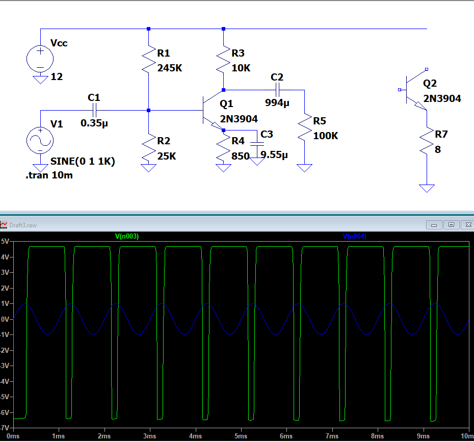
Let's test my assertion:
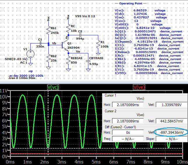
First off, yes. With an input of \$30\:\text{mV}\$ peak, we just break through my \$V_{_\text{CE}}\approx 1\:\text{V}\$ (to avoid the onset of saturation.) Close enough so that my approach is validated.
But second, notice the terrible distortion in the green curves? That's what this kind of stage does to an input signal when pushing it to its limits. This is because the voltage gain is highly variable with input signal, if the input signal deviates very far from its small signal assumption. And a \$30\:\text{mV}\$ peak obviously falsifies that assumption.
Earlier, I said the voltage gain is \$45\:\text{dB}\$. This would be truer for a \$1\:\mu\text{V}\$ input peak. But with the collector dropping to \$1.4\:\text{V}\$, the change in collector current is substantial (more than double) and this changes the voltage gain by the same factor, to almost \$53\:\text{dB}\$. Similarly, at the other end of the cycle the collector current drops by about a factor of 4 now and therefore the voltage gain drops to about \$33\:\text{dB}\$.
Those kinds of voltage gain changes mean distortion on an epic scale!
You just can't do that.
There are fixes. One fix is to dramatically reduce the input signal (I'll get to that, shortly.) Another would be to add global NFB (with another transistor added.) And another would be to place an AC emitter degeneration resistor in series with the emitter bypass capacitor. That will reduce the gain. But that's the price that has to be paid to keep this topology.
What signal level would be acceptable? That depends on how much distortion you are willing to accept. But let's say a gain variation of \$\pm 3\:\text{dB}\$ is acceptable (a factor of \$\sqrt{2}\$ in collector current, one way or the other.) Then the maximum input signal would be about \$9\:\text{mV}\$ peak!
Let's see:
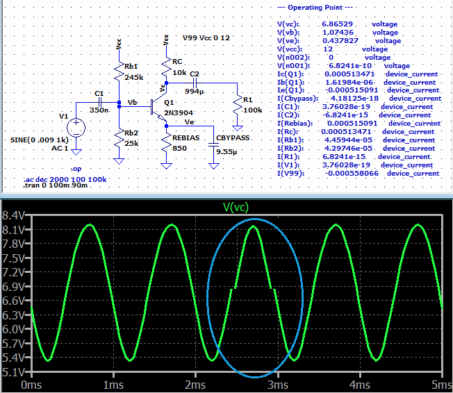
And that looks a lot better. But as you can see, where I flipped one half-cycle around in the center, it's still distorting the input signal enough to notice here.
So you have the above issues with respect to the 1st stage, which need solutions. And the 2nd stage is simply wrong and needs to be abandoned, entirely.

