1
\$\begingroup\$

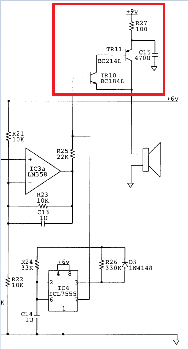
Final installment (promise!) in my set of metal detector circuit questions. This time it's the speaker driver (see images below). When I first saw this, I thought - no problem it's a sziklai pair, which the AoE describes as a super-beta darlington like combination with a lower Vbe. I also figured that the 470uF cap was just for smoothing Vcc...I was wrong (again).

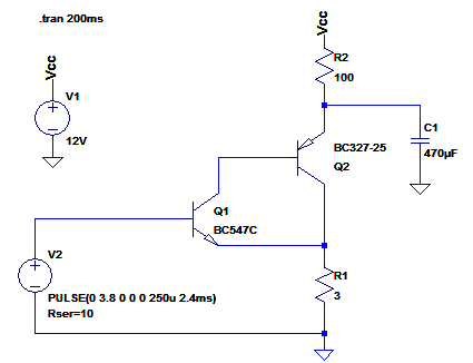
Some breadboard analysis and spice (see images below) tells the story. The cap charges up to hold the voltage at the emitter of Q2 at a saturation voltage above the collector. This (it would seem) kills the beta of Q2 and the overall beta of the sziklai pair drops to (by my calculation) around 25.

I measured the Ib flowing to Q1 on the breadboard (and spice concurs) and it's ~40mA. This all points to the same conclusion: the cap is driving the pair into saturation and the beta is reduced.

But what I can't understand is why? Why would the designer do this?

By the way, in case you're confused by the spice images, I upped the freq from the 555 to 400Hz because I found the 4Hz ticking in the original to be less effective. But, I don't think it alters the general idea of the capacitor.

Complete original documentation to be found here.

Update:

I thought I'd simulated the original circuit with a frequency of 4Hz and a 8 ohm speaker, but obviously not (or not correctly). Anyway, it seems that the speaker I'm using (4ohm 2W) is simply too heavy a load for the driver, causing the driver to saturate. Other than that the intention of C1/R2 is all of the points Jim mentions in the comments. Thankyou.

enter image description here enter image description here enter image description here

\$\endgroup\$
8
  • \$\begingroup\$ From an AC point of view the 470uF cap is connected across R2 i.e. a bypass cap. In the simulation you need to add something equivalent to R25 (22k). Putting 3.8V (10 Ohms) directly into the base of TR10 with R1 as 3 Ohms won't give the correct answers. I'd also expect the speaker to have a much higher (at least 64 Ohms) resistance given the current drive capability of the BJTs \$\endgroup\$ Commented Nov 18, 2016 at 9:56
  • \$\begingroup\$ OK, but the 40mA Ib I measured in the actual circuit (admittedly it wasn't the easiest to measure: 1 ohm resistor, scope math functions, etc) but it wouldn't have been that far out. So, the beta is reduced it would seem. I still don't get it?? \$\endgroup\$
    – Buck8pe
    Commented Nov 18, 2016 at 10:03
  • \$\begingroup\$ Also, I'm using a slightly smaller speaker than recommended. A 2W 4Ohm, which I calculated had an impedance of around 3.1 ohms. \$\endgroup\$
    – Buck8pe
    Commented Nov 18, 2016 at 10:05
  • \$\begingroup\$ The original article states 8 ohm speaker. \$\endgroup\$ Commented Nov 18, 2016 at 10:06
  • \$\begingroup\$ Yes, I know the speaker is undersized, but I wasn't sure if that would effect what was happening at C1/R2? I mean, what I don't get is why R2? If the idea was to reduce ripple on Vcc, why not just bypass the rail? \$\endgroup\$
    – Buck8pe
    Commented Nov 18, 2016 at 10:13

1 Answer 1

1
\$\begingroup\$

Your simulation is not completely showing the function of this circuit. The output of IC3a is a running at around 20kHz. The funtion of 555 and what you are calling Q1 and Q2 is to shift this frequency down to something audible. Men tend to not be able to hear 20kHz. You need to add a second signal source through the 22k resistor R25 to see what is happening. This circuit is actually a crude mixer. You also need to run your 555 pulses at 6V and the Vcc at 9 to get the intended result.

\$\endgroup\$
2
  • \$\begingroup\$ you're right, the spice circuit doesn't tell the whole story, but I knew that anyway. I understand the circuit function as a whole, but I was confused as to why the transistor pair were saturating. In the end, it was simple, the load was too heavy. It's amazing what a difference a few ohms can make! \$\endgroup\$
    – Buck8pe
    Commented Nov 18, 2016 at 13:56
  • \$\begingroup\$ Also, I'm not sure about the IC3a's output. It's really just a buffer for an earlier integration stage. So, the 20khz Rx frequency is integrated to produce slower changing "bumps". That's what C13 is all about, its amplifying the DC part of the "bump". \$\endgroup\$
    – Buck8pe
    Commented Nov 18, 2016 at 14:04

Your Answer

By clicking “Post Your Answer”, you agree to our terms of service and acknowledge you have read our privacy policy.

Not the answer you're looking for? Browse other questions tagged or ask your own question.