I have stand fans here that tend to burn out regularly because the bearings get dirty, causing friction thereby increasing the slip, which makes the stator overheat, which blows out the thermal protective fuse. That's not important at all, but made me open quite a few of those when trying to repair them by replacing the thermal fuse with a new one.
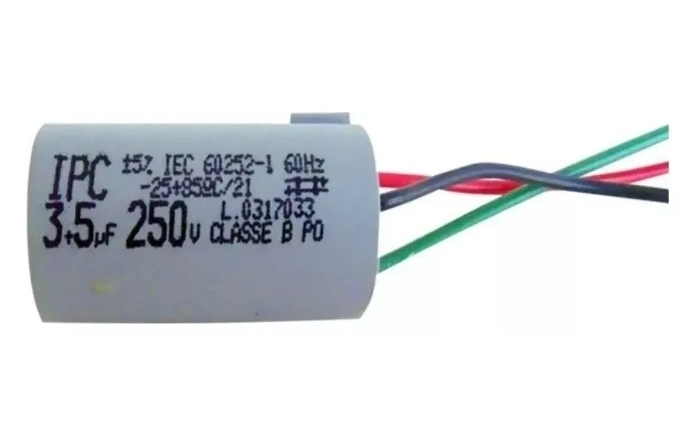
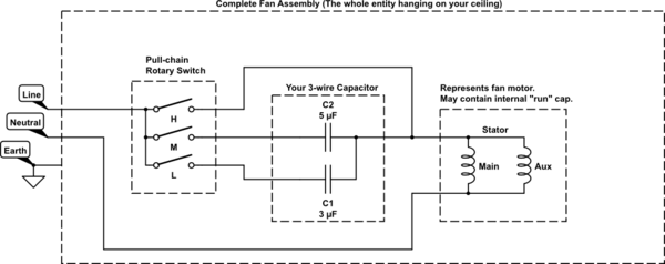
What I noticed, is that there is only one capacitor, working on one winding.
That could be the same in your fan: 1 capacitor to just get it running, and in your case 8\$\mu\$F.
Then for the speed control there are one (supposedly ground) wire and three wires to select between, with a selector switch connected to the line voltage, for speed control. Those three wires are supposedly different taps on the same stator coil to control the stator flux's strength.
In those stand fans my take is that each subsequent coil wire is part of the same main stator coil but adds some windings to it in order to lower the flux, hence to increase the slip, and so to decrease the rotational speed.
Now, with the current power electronic circuits we can directly control the voltage, and with that the flux and hence the slip and therefore the speed, so that we don't need additional windings with switches anymore.
So the capacitor probably is still necessary, but needs to be built into the ceiling fan near the electric motor itself, and to the appropriate wires. The controller might need to be connected to the coil with the lowest winding count with respect to its neutral line. Then with maximum voltage the fan might run at high speed, and voltage can be lowered by increasing the ignition angle of the triac in order to lower the average half-cycle voltage, and therefore flux, which would increase the slip and so decrease the rotational speed.


