1
\$\begingroup\$

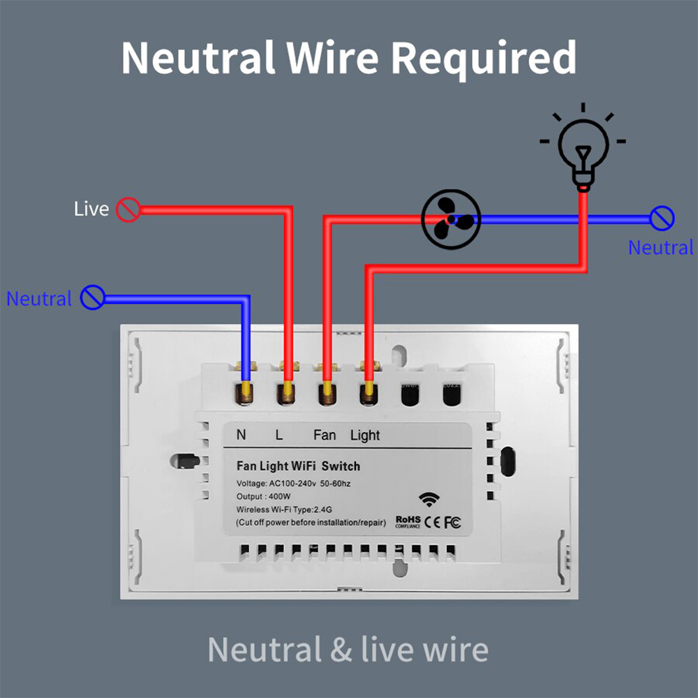
I bought this Zigbee ceiling fan controller:

enter image description here

product page

I started to wonder about what the purpose of a capacitor in a ceiling fan is.

This controller claims that it already controls the speed, and I've seen some places saying that the capacitor is for regulating the speed, and others saying that it's used to start the fan.

What is the purpose of a capacitor in a ceiling fan, and how is it affected when the controller already controls the speed? I found https://electronics.stackexchange.com/a/115912/279212 which explains that the capacitor is for a voltage drop which controls the speed. So I don't need the capacitor if the controller already does everything?

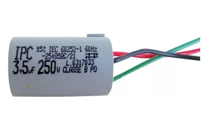
My capacitor has 3 wires. I researched and found out it's actually 2 capacitors, but it has 2 wires soldered together which makes things difficult

This is my capacitor that already works with the fan:

enter image description here

\$\endgroup\$
5
  • \$\begingroup\$ Please link to datasheet of the capacitor, or a photo of it. \$\endgroup\$
    – winny
    Commented Mar 18 at 22:07
  • \$\begingroup\$ @winny thanks, added \$\endgroup\$
    – Gatonito
    Commented Mar 18 at 22:11
  • \$\begingroup\$ Wiring diagram of previous controller may help. \$\endgroup\$
    – user263983
    Commented Mar 18 at 23:04
  • \$\begingroup\$ Please clarify your specific problem or provide additional details to highlight exactly what you need. As it's currently written, it's hard to tell exactly what you're asking. \$\endgroup\$
    – Community Bot
    Commented Mar 18 at 23:34
  • \$\begingroup\$ What is your question? I guess it's not what the capacitor does, as you found a question to that effect. Asking how to wire equipment, falls under the rule: "Questions on the use of electronic devices are off-topic as this site is intended specifically for questions on electronics design", and might be better asked on DIY.SE. \$\endgroup\$ Commented Mar 25 at 1:10

2 Answers 2

2
+100
\$\begingroup\$

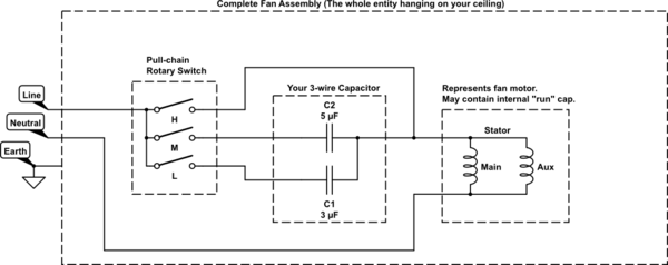
Let's start with a diagram of what your standalone fan looks like:

schematic

simulate this circuit – Schematic created using CircuitLab

This is a typical ceiling fan. You have a pull switch that sequences through 4 states: Off, High Speed, Medium Speed, and Low Speed (the order doesn't really matter and depends on the manufacturer). The pull switch determines how current actually gets to the motor which determines its speed: Bypass the cap(s) for high-speed, pass current through a series 5uF cap for Medium speed, pass current through a series 3uF cap for Low speed, or open the circuit for Off. For simplicity, I've eliminated the forward and reverse switch used for winter and summer mode. Also, it's beyond the scope of your questions.

What is the purpose of a capacitor in a ceiling fan, and how is it affected when the controller already controls the speed?

The construction of the actual motor may have included a capacitor that has nothing to do with its speed - if it does have a capacitor, it is intended to introduce a phase-shift in current with one of the coils of the stator to create a rotating magnetic field which induces a torque on the rotor. This capacitor does not exist on the schematic; not all motors need a run capacitor. But again, irrelevant for speed control which is what this is about.

The capacitor in your picture is really a package of 2 capacitors with one lead common to both. Notice the "3+5uF" marking. This is the one that actually controls the speed. It simply inserts reactance in series with the actual fan motor. You can think of this capacitor as a "lossless AC resistor" (lossless in the sense it won't dissipate power and get hot). This additional impedance reduces the current that the motor will see. The reactance for the 3uF and 5uF capacitor can be calculated by Xc = 1/(2piF*C). So at 60Hz, those reactances will be 884ohms and 531ohms, respectively.

So I don't need the capacitor if the controller already does everything?

No. You technically don't need the speed-control capacitor that comes with the fan. You would normally just set the pull-chain to the highest speed, and let your fan controller take care of the rest. As you might expect, if you don't have the chain set to the highest speed, the fan speed range will be scaled down. This may be desirable behavior if you have a super powerful fan and you want finer control with your speed controller. In your case, considering you already removed the speed capacitor, your fan won't even work unless the chain switch is set to the highest speed.

\$\endgroup\$
4
  • \$\begingroup\$ The two capacitors are soldered in parallel. Maybe there was no 8 uF available. \$\endgroup\$
    – HarryH
    Commented Mar 27 at 14:33
  • \$\begingroup\$ Yes. So, for the case where they are in parallel, wouldn't this mean they are just for regulating the speed? So isn't there a way to connect the fan and still have speed control? \$\endgroup\$
    – Gatonito
    Commented Mar 28 at 18:53
  • \$\begingroup\$ @Gatonito Yes, both the capacitors and the speed controller regulate the speed. Both can be used together. Normally, you leave the fan set to its highest speed and do the speed adjusting with the controller. You just have to connect the fan to the controller in whatever configuration provides the max speed. The controller takes care of the rest. You need to provide additional information if that is not clear cause I don't have any specific information on your fan or your current wiring set up. \$\endgroup\$
    – MOSFET
    Commented Mar 28 at 19:08
  • \$\begingroup\$ @Gatonito Did you modify the fan in anyway? Or did you leave it "stock"? \$\endgroup\$
    – MOSFET
    Commented Mar 28 at 19:09
0
\$\begingroup\$

I have stand fans here that tend to burn out regularly because the bearings get dirty, causing friction thereby increasing the slip, which makes the stator overheat, which blows out the thermal protective fuse. That's not important at all, but made me open quite a few of those when trying to repair them by replacing the thermal fuse with a new one.

What I noticed, is that there is only one capacitor, working on one winding. That could be the same in your fan: 1 capacitor to just get it running, and in your case 8\$\mu\$F.

Then for the speed control there are one (supposedly ground) wire and three wires to select between, with a selector switch connected to the line voltage, for speed control. Those three wires are supposedly different taps on the same stator coil to control the stator flux's strength.

In those stand fans my take is that each subsequent coil wire is part of the same main stator coil but adds some windings to it in order to lower the flux, hence to increase the slip, and so to decrease the rotational speed.

Now, with the current power electronic circuits we can directly control the voltage, and with that the flux and hence the slip and therefore the speed, so that we don't need additional windings with switches anymore.

So the capacitor probably is still necessary, but needs to be built into the ceiling fan near the electric motor itself, and to the appropriate wires. The controller might need to be connected to the coil with the lowest winding count with respect to its neutral line. Then with maximum voltage the fan might run at high speed, and voltage can be lowered by increasing the ignition angle of the triac in order to lower the average half-cycle voltage, and therefore flux, which would increase the slip and so decrease the rotational speed.

\$\endgroup\$

Your Answer

By clicking “Post Your Answer”, you agree to our terms of service and acknowledge you have read our privacy policy.

Not the answer you're looking for? Browse other questions tagged or ask your own question.