0
\$\begingroup\$

I have this circuit which measures if there is under/over voltage from the AC mains voltage and it consist of two parts:

Part one: measuring the input voltage (I had it cropped because it is not the main issue).

Part two: driving the relay with a red,yellow and green LEDs.

Red LED: it means there is under/over voltage. Yellow LED: A delay to check whether there is under/over voltage. Green LED: after the delay ends this means the Voltage is stable and The relay is powered ON.

The problem with this circuit, is that the relay is "chattering" after the delay ends (it gets back to the first state of the yellow LED delay) especially with inductive loads like motors(even as small as 60 Watts)

so my question: why is the "chattering" is happening and what is the solution for it?

Notes:

  • VZ is Voltage from a Zener diode which equals to 27 Volts.
  • This device works on a capacitive power supply.
  • Under/Over voltage are intended to be: 175 V and below is under voltage and 268 V and above is over voltage.
  • The Button is used the kill the delay time by discharging the capacitor.
  • I soldered on the PCB an SMD un-polarized ceramic capacitor (C3).
  • Delay goes for approximately 3 minutes until the Green LED turns on

The Circuit:

Sorry if I forgot to state/clarify anything, please feel free to ask.

\$\endgroup\$
8
  • \$\begingroup\$ Did you design in some hysteresis? (I'm not looking yet. Just asking as it is the first thing that comes to mind when you talk about levels and chattering.) \$\endgroup\$ Commented Jun 23 at 22:58
  • 2
    \$\begingroup\$ Q1: What is the supply voltage for the op-amps? Q2: What are the inputs of U1:2 connected to? Q3: For RL1, what is the coil drive requirements (voltage & current)- datasheet please? Q4: For D1 & D2: links to datasheets please. Cheers. \$\endgroup\$ Commented Jun 23 at 22:59
  • \$\begingroup\$ My first thought is the relay is too much for the LM324. Need a datasheet for the relay. \$\endgroup\$
    – user319836
    Commented Jun 23 at 23:03
  • \$\begingroup\$ @periblepsis I think R7 and R11 do this job they make a schmitt trigger here \$\endgroup\$ Commented Jun 23 at 23:06
  • 2
    \$\begingroup\$ @HazardousVoltage May I suggest editing your OP (question) to include all the new information required. Cheers. \$\endgroup\$ Commented Jun 23 at 23:13

2 Answers 2

1
\$\begingroup\$

When your load is applied the measured voltage will drop a bit (or maybe a lot) so you can get chattering as a result of that. So it's important you have adequate hysteresis for the lower trip point. You should have some for the upper trip point too, but it's not as important since the overvoltage will further increase when the load is removed.

I would also suggest using a Schottky diode only for D7. A lot of chips behave rather badly when you drag any pin below ground. Or use a series diode, losing a bit of voltage. Or drive the relay with a transistor.

\$\endgroup\$
5
  • \$\begingroup\$ Can you please guide me where should the hysteresis be applied, should I increase R10? \$\endgroup\$ Commented Jun 23 at 23:24
  • \$\begingroup\$ I tried using a transistor to drive the relay directly from pin 8 of the op-amp, connected the collector to the ground pin of the relay (I removed the ground and put the collector pin instead) but it resulted in tripping the green led even before reaching the under voltage \$\endgroup\$ Commented Jun 23 at 23:30
  • \$\begingroup\$ I don't actually see where the measured voltage is compared - maybe you elided it. \$\endgroup\$ Commented Jun 23 at 23:35
  • \$\begingroup\$ I included it now, since it is necessary. It is measured as under voltage at D4 and over voltage at D5 using two comparators. \$\endgroup\$ Commented Jun 23 at 23:37
  • \$\begingroup\$ The mechanism works like this: input voltage comes from the mains rectified using D3 and gets divided by (R3,R15 and R4) and smoothed through C2 then enters to the Under and Over voltage comparators measuring in reference to the zener diodes D4 and D5 if it is in between region of 4.7 V and 6.8 V then the circuit will go through a 3 min Delay after that it turns on if it stayed in that region. if it went higher than 6.8 V or lower than 4.7 V, then the Red LED will turn ON \$\endgroup\$ Commented Jun 23 at 23:41
0
\$\begingroup\$

Seems you need what is known as a "window comparator". This is just two separate comparators, each looking at the same input signal and comparing it to separate thresholds, Vlow and Vhigh. This provides two separate outputs: one to tell you if the input is below Vlow, and another to tell you if the input is above Vhigh. The benefit of this compared to your existing design is that you get full control over all the variables involved: you can independently adjust both the threshold and hysteresis for each comparator.

Here is a link to a decent app note for a window comparator:
https://www.ti.com/lit/ug/tidub01/tidub01.pdf

You will note that the schematic in this publication has two problems in your application:
(a) The outputs are connected together. I suggest keeping them separate.
(b) Does not include any hysteresis around each comparator; I would suggest adding a small amount of positive feedback (hysteresis) to ensure stability; say, between 0.1 and 1% should be OK, this depends on precisely where you want the output to trip.

Some simple logic after the comparator outputs can then be used to control the three LEDs and the relay as required.

UPDATE AFTER OP IMPROVED THE QUESTION

Your circuit needs hysteresis on BOTH comparators. So you need to add four (4) new resistors, as shown in the mark-up schematic below:
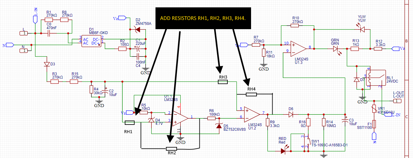
enter image description here

Here are some values that I suggest you try for each resistor. These are selected based on providing 1% hysteresis for each comparator.

RH1, RH3: 10kΩ
RH2: 10MEG Ω
RH4: 10MEG Ω

NOTE: The op-amp you have used for the comparators (LM324S) may not be sufficiently accurate for this application; the input bias currents (90nA typ, 250nA max) are not insignificant when compared to the currents associated with the hysteresis (~2 uA). This may cause the hysteresis to be very dependent upon the op-amp input current, which is not a tightly controlled parameter.

You can improve this situation by placing a new op-amp as a voltage-follower buffer after C2 to provide a low-impedance for the signal to the window comparator, and reducing the impedance of the signal to each comparator to about 1kΩ (it is now at 40kΩ = R4 + RH1, & RH3). This change allows RH2 and RH4 to be reduced significantly to null out the effects of op-amp input bias current variation.

Since the LM324 package contains four (4) op-amps, you should have a spare op-amp available to do this. If you don't have a spare op-amp available now, then I suggest re-purposing U1:3 for this role, and replacing U1:3 with some simple transistor logic to drive the outputs (LEDs and Relay) as required from the outputs of the comparators.

\$\endgroup\$
6
  • \$\begingroup\$ The measuring part works correctly without any problem, it works similarly like the Window Comparator, it takes one input signal to two different Comparators, one of them measures the under voltage, the other one measures the over voltage. (a) Can you please explain which outputs should be separated? (b) do you mean I need to increase R10? \$\endgroup\$ Commented Jun 23 at 23:22
  • \$\begingroup\$ There are two different comparators in your circuit? Sorry, I can't see them. All I see is one comparator. U1:3, which has a complex feedback circuit that seems to be trying to set up a wide hysteresis. Using an LED in the feedback of a comparator is not a good way of getting precise control over the switching thresholds of said comparator. \$\endgroup\$ Commented Jun 23 at 23:29
  • \$\begingroup\$ @HazardousVoltage Also, U1:3 is not really a comparator, it is an op-amp which is being reluctantly pressed into a role for which it is ill-suited. Suggest you read the app note I provided, then have a think about your circuit requirements again. Cheers. \$\endgroup\$ Commented Jun 23 at 23:31
  • \$\begingroup\$ my bad! I will reupload the full circuitry so it will be crystal clear. \$\endgroup\$ Commented Jun 23 at 23:32
  • \$\begingroup\$ now you can see here, do you mean I need hysteresis on the Op-amp side or the comparator side? \$\endgroup\$ Commented Jun 23 at 23:35

Your Answer

By clicking “Post Your Answer”, you agree to our terms of service and acknowledge you have read our privacy policy.

Not the answer you're looking for? Browse other questions tagged or ask your own question.