0
\$\begingroup\$

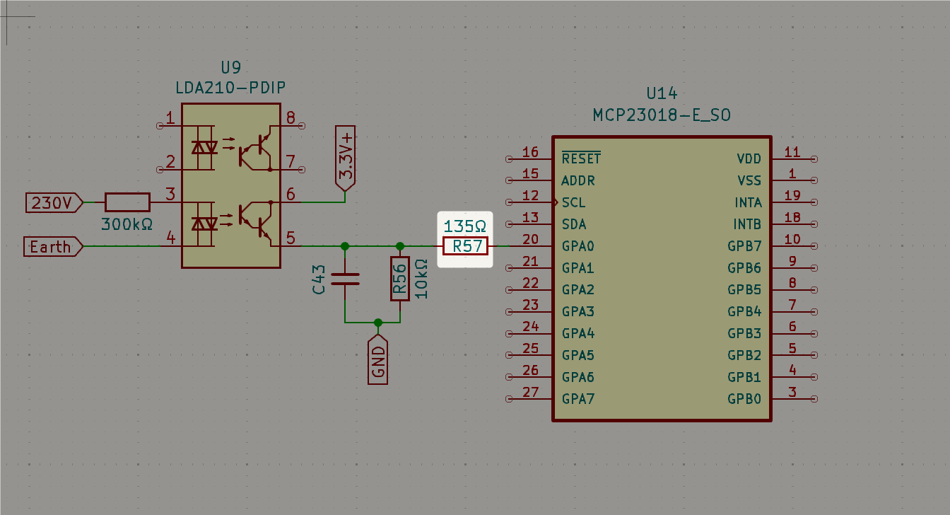
Given the following circuit to sense voltage.

I am trying to calculate the value that the highlighted resistor should have (or to figure out if it is needed at all)

schematic

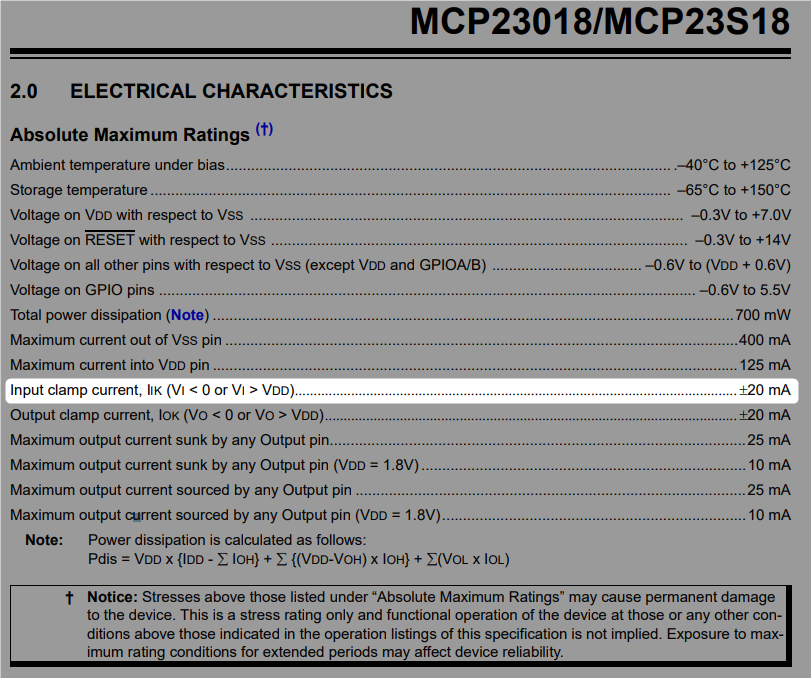
The MCP23018 is an IO port expander via I2C that I will connect to an ESP32. Since the 3.3V comes directly from the power supply, my intuition tells me that I should limit current before the MCP23018. In the datasheet it says that the input will be clamp at 20mA, so I used that to calculate my resistor:

*[Edited]
V = 3.3V - 0.6V (Darlington voltage drop) 
R = V / I
R = 2.7V / 20mA = 135Ω

enter image description here

Do I need that resistor? If yes, Is my calculation correct?

Links
LDA210 datasheet: link
MC23018 datasheet: link
My full schematic: link

\$\endgroup\$
8
  • \$\begingroup\$ What makes you think this will work with EMI, and subthreshold noise and emitter follower drop from a Darlington? Not to mention overvoltage on the 300k with ~3kV +transients. Try again. \$\endgroup\$
    – D.A.S.
    Commented Aug 18 at 16:16
  • \$\begingroup\$ Hi @D.A.S. In reality the 300kΩ resistor is 2x150kΩ and a fuse in case there is an overcurrent (you can see it in the full schematic). I have that circuit working on my bench, but I have no idea on the EMI and subthreshold noise, I will try to research a bit further, any tips are welcome - Thanks! :) \$\endgroup\$ Commented Aug 18 at 16:23
  • \$\begingroup\$ @CarlosGarcia, do you have the case where the VDD to the IO expander is 0V and the voltage on GPA0 is 3.3V? \$\endgroup\$
    – sai
    Commented Aug 18 at 16:55
  • 1
    \$\begingroup\$ No, your calculation isn't correct. The GPIO has a very high impedance impedance so very little current will flow into it, even if you were to connect it directly to 3.3V. In your calculation you treated the collector-emitter path of the transistor as a resistor but that's not valid. \$\endgroup\$
    – td127
    Commented Aug 18 at 17:39
  • 1
    \$\begingroup\$ @CarlosGarcia, in your case, since VI is between 0 and VDD, you don't need the resistor. \$\endgroup\$
    – sai
    Commented Aug 19 at 5:01

1 Answer 1

1
\$\begingroup\$

You are trying to read a digital 3.3V signal with a digital 3.3V IO pin.

The resistor is useless and can be removed. Unless there is some reason to have it there, such as 3.3V from some power supply being fed through the input to an unpowered chip with 3.3V turned off.

So no, you don't need it and the calculation is wrong, except when the chip is unpowered and you forcibly feed it 3.3V via IO pin and the chip supply is shorted to ground.

If the signal would come from a digital IC, the output of that digital IC would also "just" be directly through a transistor inside the chip to the chip power supply.

\$\endgroup\$
2
  • \$\begingroup\$ Thank you @Justme, it makes sense! This might be asking too much... but... could you please elaborated a bit on "except when the chip is unpowered" What is different when chips are unpowered? Thanks! \$\endgroup\$ Commented Aug 18 at 17:11
  • 1
    \$\begingroup\$ @CarlosGarcia Basic usage of chips, do not feed in voltages to data pins that are beyond supply voltages. Which means, if chip is powered by 3.3V supply, do not input 5V. If chip is powered by 0V supply, do not input 3.3V. Exceptions apply and always refer to data sheet what is allowed and what isn't, or you risk damage to chips. \$\endgroup\$
    – Justme
    Commented Aug 18 at 18:16

Your Answer

By clicking “Post Your Answer”, you agree to our terms of service and acknowledge you have read our privacy policy.

Not the answer you're looking for? Browse other questions tagged or ask your own question.