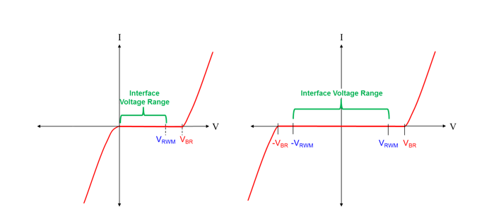
Generally TVS diode curves are shown as
 (Source https://www.ti.com/document-viewer/lit/html/SSZT784)
With the left most being a uni directional and right being bi directional TVS diode.
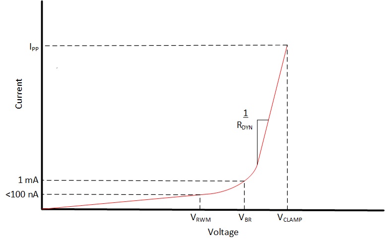
TVS diodes have a
- Working or Reverse stand off voltage and this should be less than or equal to your voltage of operation (VRWM)
- Breakdown voltage where if the voltage across your load meets this voltage, the TVS diode will begin to conduct in reverse bias mode (VBR)
- Clamping voltage where if the voltage at the source continues to increase (e.g. due to a momentary surge) then voltage across your load will remain at this clamped voltage and the TVS diode will conduct more current through it in order to do so (VC)
 (Source TVS diode specs - clamping voltage lower than breakdown voltage?)
However when looking for a TVS diode to protect a 3.3V Ethernet data line on the Ethernet PHY side of the magnetics. I have come across some TVS diodes with a clamping voltage less than the Breakdown voltage.
Reading this stack exchange question and answer TVS diode specs - clamping voltage lower than breakdown voltage? I understand this 'snapback' behaviour (as shown below) but why?
 (Source https://blog.mbedded.ninja/electronics/components/diodes/tvs-diodes/)
For example this TVS diode https://www.mouser.co.uk/datasheet/2/1057/PS1703_D32-3498786.pdf on page 2 it says
- V reverse stand off = 3.3V (MAX)
- V breakdown = 11V
- V clamp = 3.4V
The device I want to protect (Ethernet PHY) has an absolute max voltage on the digital input pins of 3.6V so a V clamp of 3.4V is perfect but the breakdown is 11V.
Is this TVS diode still okay to use for my purposes? Is it reasonable to assume that the 11V breakdown 'knee' voltage would be only for a moment and then the TVS would operate in clamping mode and although the device I wish to protect says it has an Absolute maximum of 3.6V, this is 3.6V continuous and would survive an 11V momentary spike?
In my mind, ideally I would find a TVS with
- V reverse stand off = 3.3V
- V breakdown - 3.4-3.5V
- V clamp 3.5-3.6V
But I cannot seem to find one that meets this? Am I missing something or this does not exist hence the reason for the 'snapback' TVS diode? If this is not the case, why would you need a snapback TVS diode?
